
HDI PCB Thermal Management: Design Guide & Best Practices

Importance of HDI PCB Thermal Management
The high-density interconnect structure of HDI PCBs introduces distinct thermal challenges that demand specialized design strategies. Fine-pitch traces, microvias, and thin dielectric layers create constrained thermal pathways that limit natural heat dissipation. High-power components such as BGA and CSP packages concentrate thermal energy in smaller footprints, making effective HDI PCB thermal management essential for long-term reliability.
Inadequate thermal design triggers progressive failure mechanisms that compromise assembly performance. These failures include solder joint fatigue, delamination between dielectric layers, microvia barrel cracking, and signal integrity degradation from temperature-dependent impedance shifts. Most thermal failures manifest after extended field operation rather than during initial testing, making proactive heat dissipation design critical for product longevity.
Effective thermal management in HDI structures requires establishing predictable heat flow from concentrated sources to dissipation zones. This integration must occur during early design stages across stackup definition, via architecture, and component placement rather than as post-layout corrections.
Thermal Path Design in HDI PCB
Heat Flow Architecture
Effective thermal path design in HDI PCB structures begins with mapping heat flow from generation points through conductive pathways to dissipation surfaces. Heat flows preferentially through copper layers and filled vias rather than low-conductivity dielectrics. The thermal path extends from component pads through localized copper planes, then through thermal vias to inner or outer layers with greater thermal mass.
This staged approach prevents thermal bottlenecks that create localized hotspots. Designers must establish intentional thermal highways that guide heat away from critical components toward heat-spreading planes and external interfaces.
Core Elements of HDI Heat Dissipation Design
Successful thermal management in HDI PCB assemblies requires coordinated implementation of multiple design elements:
- Copper plane spreading – Internal ground or power planes positioned adjacent to high-power components provide low-resistance lateral heat distribution with thermal conductivity exceeding dielectrics by 200×.
- Thermal via arrays – Vertical via conduits connect component pads to heat-spreading planes, with via-in-pad configurations offering the shortest thermal path despite requiring specialized filling processes.
- Stackup symmetry – Balanced layer arrangements prevent warpage from differential thermal expansion while optimizing dielectric thickness to reduce thermal resistance.
- Component placement strategy – Positioning high-power devices near thermal via zones and heat-spreading layers minimizes thermal path length.
Thermal Via Design for HDI PCB
Blind and buried microvias serve dual functions as signal interconnects and thermal conduits when designed with copper-fill materials. Copper-filled vias deliver superior thermal conductivity compared to unfilled alternatives. Stacked or staggered via configurations enable heat transfer through multiple layer transitions while maintaining compact footprints, with thermal effectiveness scaling directly with via count and fill quality.

Copper Thickness and Distribution in HDI Thermal Design
Copper Weight Selection
Base copper thickness directly influences thermal spreading capacity within each PCB layer. Standard 1 oz copper provides adequate performance for moderate power densities, while 2 oz or 3 oz copper significantly enhances heat spreading for high-power applications. Thicker copper reduces thermal resistance but requires wider trace spacing to maintain voltage isolation and increases manufacturing complexity.
Selective copper plating enables targeted thickness increases in thermal-critical zones while maintaining standard copper for signal routing areas. This approach optimizes HDI heat dissipation design without incurring full-panel heavy copper costs.
Balancing Thermal and Electrical Performance
Different functional layers require distinct copper thickness strategies to optimize both thermal management and signal integrity:
- Signal layers – Thinner copper (0.5-1 oz) maintains precise impedance control and minimizes skin effect losses for high-frequency signals.
- Power planes – Heavier copper (2-3 oz) enhances thermal spreading and reduces DC resistance without compromising impedance matching requirements.
- Thermal zones – Selective plating in high-power component areas provides localized heat dissipation enhancement.
- Copper balancing – Uniform copper distribution across panels prevents warpage from differential thermal expansion during lamination and assembly.
Copper distribution uniformity becomes critical in HDI constructions where thin overall thickness increases susceptibility to thermally induced deformation. Designers should implement copper balancing patterns in sparse routing regions to maintain mechanical stability under thermal stress.
Material Selection for HDI PCB Thermal Management
Dielectric Thermal Properties
The thermal conductivity of base dielectric materials establishes the fundamental limit for through-thickness heat transfer in HDI PCB stackups. Standard FR-4 exhibits thermal conductivity around 0.3-0.4 W/mK, while high-performance alternatives including polyimide, BT resin, or specialized high-thermal-conductivity laminates provide modestly improved performance. Material selection must balance thermal requirements against electrical properties including dielectric constant, loss tangent, and coefficient of thermal expansion.
Metal-core or insulated metal substrate constructions offer substantially enhanced thermal performance by incorporating aluminum or copper plates within the stackup. These hybrid structures enable direct heat transfer to external heat sinks while maintaining electrical isolation through thin dielectric layers.
HDI Stackup Thermal Performance Optimization
The physical arrangement of copper and dielectric layers determines thermal pathway effectiveness from component surfaces through the complete board thickness. Placing continuous copper planes adjacent to mounting surfaces minimizes initial thermal path length from heat sources. Sequential lamination in HDI manufacturing creates discrete thermal interfaces at each boundary, and these interfaces introduce cumulative thermal resistance across multiple layer transitions.
Strategic positioning of thermal via connections between core and buildup layers ensures continuous heat flow paths through complete stackup depth. Advanced HDI stackup thermal performance requires holistic optimization that considers both material thermal conductivity and architectural efficiency of the layer sequence.
Thermal Simulation and Analysis in HDI PCB Design
Computational Modeling Tools
Modern thermal simulation packages including ANSYS, HyperLynx, FloTHERM, and ICEpak enable prediction of temperature distribution before prototype fabrication. These finite element or computational fluid dynamics tools require accurate input parameters including component power dissipation, copper geometry, material thermal conductivity, and boundary conditions representing the operational environment. Result fidelity depends critically on input accuracy and mesh resolution used to discretize the geometry.
Thermal simulation in HDI PCB design should encompass both steady-state temperature rise analysis and transient thermal response to pulsed power profiles. Steady-state analysis identifies peak operating temperatures and validates thermal margins, while transient analysis reveals thermal time constants during power cycling events.
Simulation Validation Process
Effective thermal analysis and heat dissipation modeling requires systematic validation through physical measurement:
- Infrared thermal imaging – Non-contact temperature mapping across assembled PCB surfaces identifies actual hotspot locations and intensity.
- Embedded thermocouples – Direct temperature measurement at critical component junctions validates peak temperature predictions.
- Model correlation – Systematic comparison between predicted and measured temperatures establishes confidence levels and identifies refinement areas.
- Design iteration – Calibrated thermal models enable evaluation of design variants across different operating conditions with minimal prototype cycles.
Early identification of thermal issues through simulation prevents costly redesigns and accelerates time to market for thermally challenging HDI PCB thermal management applications.

Thermal Reliability Testing for HDI PCB
Accelerated Thermal Stress Testing
Accelerated thermal cycling subjects assembled HDI PCBs to repeated temperature excursions that simulate extended field exposure in compressed timeframes. Standard protocols including thermal shock testing, temperature cycling, and highly accelerated life testing impose thermal stress that reveals latent failures in thermal pathways, solder joints, and dielectric interfaces. These thermal reliability testing methods expose design weaknesses before volume production and validate thermal management strategies.
Thermal fatigue manifests differently across HDI structures depending on via architecture, copper thickness, and material systems. Microvia reliability under thermal cycling depends on barrel plating quality, fill completeness, and thermal expansion mismatch between via-fill material and surrounding dielectric.
Environmental Degradation Prevention
Elevated temperature and humidity accelerate electrochemical migration phenomena including conductive anodic filament formation between adjacent conductors. Effective thermal design that maintains lower operating temperatures reduces degradation kinetics. CAF prevention by thermal design involves limiting peak temperatures, selecting stable dielectric materials with low ion mobility, and ensuring adequate spacing in thermally stressed regions.
Qualification testing should combine thermal and humidity stress to evaluate complete failure modes relevant to field operation. Understanding interactions between thermal and environmental factors enables design decisions that optimize both HDI PCB reliability and long-term performance under realistic use conditions.
Practical HDI PCB Thermal Management Recommendations
Early-Stage Design Integration
Incorporating thermal analysis during initial schematic and layout planning prevents architectural issues that become difficult to resolve later. Component placement should position high-power devices near thermal via zones and avoid clustering heat sources in confined areas. Early collaboration with HDI manufacturers regarding copper weight capabilities, via-fill processes, and stackup thermal conductivity ensures design strategies align with manufacturing process capabilities.
Thermal design reviews should occur at multiple milestones including post-placement, post-routing, and pre-release stages to validate that thermal pathways remain intact and component temperatures stay within specified limits across all operating modes.
Manufacturing Process Coordination
Successful HDI heat dissipation design requires close coordination between design intent and fabrication capabilities:
- Copper specification – Confirm minimum copper clearances and achievable copper weights for high-current power planes and thermal pours.
- Via-fill processes – Ensure complete void-free filling to maximize thermal conductivity in thermal via applications.
- Selective plating – Verify manufacturer capability for selective copper plating before finalizing thermal zone definitions.
- Stackup feasibility – Review proposed layer constructions for thermal via connections between core and buildup layers.
Integration of electrical, mechanical, and thermal design constraints requires cross-functional collaboration throughout development cycles. The most effective thermal solutions emerge when thermal considerations influence component selection, PCB stackup definition, and assembly process planning from project inception.
Conclusion
Effective HDI PCB thermal management integrates material selection, copper distribution, and via-based heat pathways with simulation-driven design. Due to limited thermal dissipation in dense structures, designers must optimize heat flow, copper thickness, and stackup conductivity. Establishing efficient thermal routes from heat sources to dissipation zones—and collaborating closely with manufacturers—ensures reliable, manufacturable performance.
Highleap Electronics provides comprehensive HDI PCB thermal management solutions:
- Advanced stackup planning – Optimized layer arrangements and dielectric selections that balance thermal conductivity with electrical performance requirements.
- Thermal via engineering – Complete via-fill processes including copper plating that maximize heat transfer through HDI structures.
- Simulation support – Thermal modeling and analysis services that predict temperature distribution and validate design effectiveness.
- Manufacturing expertise – Selective copper plating and heavy copper capabilities for thermal zone optimization.
- Design collaboration – Engineering support for component placement, thermal path design, and reliability validation.
Our engineering team works closely with customers to develop thermal management strategies that meet demanding performance requirements for high-reliability applications while maintaining cost effectiveness and production efficiency. Contact our team to discuss your HDI thermal design requirements.

Recommended Posts
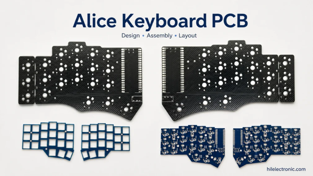
Alice Keyboard PCB Manufacturer | Custom Ergonomic Layout
An Alice keyboard PCB manufacturer must translate an...
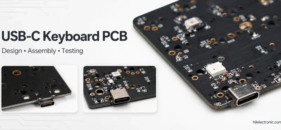
USB-C Keyboard PCB Manufacturer | ESD & Power Protection
A USB-C keyboard PCB manufacturer must control the...

Per-Key RGB Keyboard PCB Manufacturer & LED Assembly
A per-key RGB keyboard PCB manufacturer must control far...

Ortholinear Keyboard PCB Manufacturer | Custom Grid Layout
An ortholinear keyboard PCB manufacturer must preserve a...
How to get a quote for PCBs
Let‘s run DFM/DFA analysis for you and get back to you with a report. You can upload your files securely through our website. We require the following information in order to give you a quote:
-
- Gerber, ODB++, or .pcb, spec.
- BOM list if you require assembly
- Quantity
- Turn time
In addition to PCB manufacturing, we offer a comprehensive range of electronic services, including PCB design, PCBA, and turnkey solutions. Whether you need help with prototyping, design verification, component sourcing, or mass production, we provide end-to-end support to ensure your project’s success.
For PCBA services, please provide your BOM (Bill of Materials) and any specific assembly instructions. We also offer DFM/DFA analysis to optimize your designs for manufacturability and assembly, ensuring a smooth production process.