
Back to blog
Effective Techniques for Preventing Open and Short Circuits in PCB Manufacturing

There is a similar open circuit problem in Gerber:In the PCB outer layer gerber file, the outer layer line has a broken wire head
Understanding the concepts of open circuits and short circuits is fundamental for anyone working with electrical systems or PCB design. An open circuit occurs when there is a break or interruption in the conductive path, preventing current from flowing through the circuit. Unlike a closed circuit, which allows current to travel freely and power devices, an open circuit results in no current flow. On the other hand, a short circuit happens when there is an unintended low-resistance path in the circuit, causing a large amount of current to flow unrestricted. Recognizing and addressing both open and short circuits is crucial for troubleshooting and ensuring the reliability and safety of electronic devices.
What is an Open Circuit?
An open circuit is a state in an electrical circuit where the path for current flow is interrupted, preventing the current from reaching its intended destination. Unlike a closed circuit, which allows current to flow freely, an open circuit is characterized by a break or discontinuity in the circuit.
Characteristics of Open Circuits
- No Current Flow: In an open circuit, the current is zero because the continuous path required for current flow is broken.
- Voltage Presence: Despite the lack of current, there can still be a voltage drop across the open points in the circuit.
- Infinite Resistance: The resistance in an open circuit is effectively infinite, as there is no conductive path for current.
Causes of Open Circuits
Open circuits can occur due to various reasons, including:
- Loose Connections: Poorly connected wires or components can break the circuit.
- Broken Wires: Physical damage to wires can create a gap in the circuit.
- Faulty Components: Components such as resistors, capacitors, or transistors can fail, causing an open circuit.

The distance between the BGA hole and the copper sheet in the gerber file of the inner layer of the PCB is small. After optimization, it is necessary to manually add routing to maintain the original network.
Open Circuit vs. Short Circuit in PCB Design
In the realm of PCB (Printed Circuit Board) design, comprehending the distinctions between open circuits and short circuits is crucial for ensuring the reliability and functionality of electronic systems. Both phenomena represent different types of faults that can severely impact the performance of electronic circuits.
Open Circuit
An open circuit occurs when there is a break or discontinuity in the conductive path within a PCB, preventing current from flowing through the circuit. Here are the key characteristics of an open circuit:
- No Current Flow: In an open circuit, the flow of electric current is completely halted. This means the current is zero (I = 0) because the path for current to travel is interrupted.
- Infinite Resistance: The resistance in an open circuit is extremely high, theoretically approaching infinity. This is because there is no complete path for current to pass through, which creates an open gap.
- Voltage Presence: Despite the absence of current, voltage can still exist across the points of discontinuity. This is due to the potential difference between the open ends.
Short Circuit
A short circuit, on the other hand, occurs when there is an unintended low-resistance path in the circuit, allowing a large amount of current to flow unrestricted. Here are the key characteristics of a short circuit:
- High Current Flow: In a short circuit, the current flow is exceedingly high, often limited only by the power source’s capacity. Ideally, the current can approach infinity, posing significant risks.
- Low Resistance: The resistance in a short circuit is minimal, approaching zero ohms. This low resistance path bypasses the intended circuitry, leading to excessive current flow.
- No Voltage Drop: The voltage across the terminals of a short circuit is zero because the potential difference is nullified by the low resistance path.
Importance of Understanding Both
Grasping the differences between open and short circuits is essential for anyone involved in PCB design and electronic troubleshooting. Each type of fault poses distinct challenges and risks:
- Troubleshooting: Identifying whether a fault is an open or short circuit is the first step in troubleshooting. Open circuits can result in non-functional components or devices, while short circuits can cause components to overheat or even catch fire due to excessive current.
- Maintenance: Regular maintenance and inspection can prevent both types of faults. Ensuring proper soldering, avoiding physical damage to PCB traces, and using quality components are key practices.
- Safety: Short circuits, in particular, are hazardous. They can lead to overheating, fires, and damage to electronic components. Understanding these risks helps in designing safer and more reliable PCBs.
Understanding the nuances between open and short circuits in PCB design is fundamental for ensuring the performance, reliability, and safety of electronic systems. By recognizing these faults and implementing preventive measures, engineers and technicians can maintain the integrity of their designs and avoid costly and dangerous failures.
How Do CAM Engineers Check for Open Circuits in PCB Gerber Files?
As a CAM engineer, checking for open and short circuits in PCB Gerber files is a crucial step to ensure design accuracy and prevent manufacturing issues. Here is a detailed guide on how to check for open circuits in PCB Gerber files:
- Use Professional CAM Software
Professional CAM software like Genesis, Ucamco Ucam, and CAM350 offers powerful tools for inspecting and analyzing Gerber files.
- Import Gerber Files
Import all relevant Gerber files into the CAM software, including: characters, solder mask, circuitry, drilling, outline, and panelization.
Ensure all layers are correctly imported and aligned. Pay special attention to the slot layer, as many customers prefer to list the slot layer separately. Verify the hole table information carefully, as errors in drilling can lead to complex and error-prone file modifications later.
- Perform Connectivity Check
CAM software typically includes automated connectivity check tools. Here are the specific steps for some popular CAM software:
-
In Genesis:
- Open Genesis and import the Gerber files.
- Use the “Electrical Test” module and select “Connectivity Check.”
- The system will automatically scan all imported layers to detect connections between pads and traces, identifying potential open circuits.
- Review the report to pinpoint specific open circuit locations and mark them in the software.
-
In Ucamco Ucam:
- After importing the Gerber files, go to the “Analysis” menu.
- Select the “Netlist Comparison” function to compare the design netlist with the netlist generated from the Gerber files.
- The system will automatically detect connectivity issues, generate a report, and highlight problem areas.
-
In CAM350:
- After importing the Gerber files, go to the “Tools” menu.
- Select “Netlist Extract” to extract the actual connection netlist.
- Use the “Netlist Compare” function to compare the extracted netlist with the design netlist to identify open circuits.
- Review the report to locate specific open circuit issues.
- Manual Inspection of Critical Areas
In addition to automated checks, manually inspecting critical areas is essential:
- Connector Pins: Manually check each pin of connectors to ensure proper connections.
- Power and Ground Lines: Carefully inspect the paths of power and ground lines to ensure continuity.
- Critical Signal Paths: Manually verify critical signal paths, such as clock signals and data buses.
- Perform Design Rule Check (DRC)
Use the DRC feature in the CAM software to automatically detect design rule violations, including open and short circuits. For any file modifications, perform a comprehensive check of all files, not just the modified sections. Always compare the modified files with the original CAD files.
- Compare Netlists
Compare the design netlist (from PCB design software) with the actual netlist extracted from the Gerber files to ensure consistency. This step must be thoroughly executed, ensuring that issues such as network problems caused by board edge wrapping are completely resolved before proceeding.
- QA
For orders with network issues, if the order system does not note the cause, open a repair order in the order system. CAM engineers must verify and clear the issues before passing them to the QA department. Employees should not privately discuss the reasons behind PCB network issues to prevent problematic orders from reaching the production department, thereby truly reducing PCB open and short circuit issues.
To check for open circuits in PCB Gerber files, CAM engineers need to use professional CAM software to perform automated connectivity checks, design rule checks, and manual inspections. By following these steps, you can ensure the accuracy of PCB designs, prevent open circuit issues during manufacturing, and improve the reliability and performance of the circuit board.

PCB network issues
Open circuit and short circuit problems in high frequency boards
Difficulties in CAM production of high-frequency boards
1. High-precision graphics processing
In the process of high-frequency PCB production, high-precision graphics processing is crucial. Since high-frequency signals are extremely sensitive to tiny defects on the circuit board, any slight error in the etching process may cause an open circuit or a short circuit. For example, a small copper bridge or insufficient etching may cause a short circuit during high-speed signal transmission, while excessive etching may cause an open circuit. When processing these fine graphics, CAM engineers need to use high-precision etching and inspection equipment to ensure that the width and spacing of each line are within the allowable tolerance range, which places extremely high demands on the accuracy of equipment and processes. When designing high-frequency circuit boards, many designers output Gerber files with many zero-pitch networks, especially those composed of many independent small copper foils, and there are many SMD disks on them, which makes it difficult for CAM engineers to judge the network. For this kind of situation, it is recommended to make a large copper foil with the same network to facilitate CAM to judge the network.
2. Interlayer alignment and stacking technology
Multi-layer high-frequency PCBs require precise interlayer alignment, which poses a great challenge to the production process. Any interlayer misalignment may cause short circuits or open circuits between different layers. In addition, high-frequency boards often use multi-layer designs to reduce signal interference and improve electrical performance, which requires that each layer must be accurately aligned during the stacking process. CAM engineers need to use high-precision alignment equipment and technology during the stacking process to ensure that each layer is strictly aligned to avoid electrical failures caused by inter-layer misalignment.
Optimization measures for PCB designers
1. Accurate design and simulation
In order to cooperate with the high-precision graphics processing of CAM engineers, PCB designers should ensure the accuracy of every detail during the design stage. This includes using high-resolution design tools for routing and conducting comprehensive electrical simulations to verify the feasibility of the design. Designers should pay special attention to the width, spacing and via positions of signal traces to ensure that they meet the design specifications of high-frequency PCBs and reduce the risk of open circuits and short circuits.
2. Standardized and normalized design
Designers should try to adopt standardized and normalized design principles to simplify the production process for CAM engineers. For example, use standard impedance control technology and conventional stacking structures to reduce complexity. In addition, by working closely with CAM engineers and understanding their difficulties in Gerber file production, designers can make adjustments and optimizations during the design stage, such as avoiding overly complex trace graphics and ensuring reliable connections at key nodes, thereby reducing risks during the manufacturing process.
Effective Communication with CAM Engineers
To further ensure the manufacturability of high-frequency PCBs, PCB designers should maintain effective communication with CAM engineers throughout the design process. This collaboration helps in identifying potential manufacturing issues early and allows for timely adjustments to the design. By sharing detailed design intentions and constraints, designers can help CAM engineers better understand the critical aspects of the PCB, leading to more accurate and reliable production outcomes.

In the inner layer gerber file of the PCB, the isolation zone between different networks is too small
How Highleap Electronics Avoids PCB Open and Short Circuit Issues
Highleap Electronics takes several measures to avoid PCB open and short circuit issues:
Measures for PCB Designers
PCB designers need to pay special attention to the width and spacing of traces during the design stage. Choosing appropriate trace width and spacing based on current-carrying capacity and voltage level can effectively reduce the risk of short circuits. It’s advisable to keep the spacing of thermal pads slightly larger than the standard value. For modified files, special attention should be given to via issues and whether the output file parameters are consistent with the previous ones. Additionally, high-frequency signals are particularly sensitive to sharp turns in the path; such turns can increase signal reflection and crosstalk, and may also cause open circuits due to physical stress. Therefore, designers should avoid sharp turns and use smooth, curved paths to maintain signal integrity and electrical performance stability.
Measures for CAM Engineers
CAM engineers should use high-precision graphic processing tools and etching equipment when handling Gerber files to ensure that the width and spacing of each trace meet design specifications. Any points of doubt should be promptly recorded on the engineering order. For issues that involve multiple modifications, thorough checks are essential. Highleap Electronic’s engineering department requires that any modifications to Gerber files must be fully analyzed and compared with the original CAD files by each engineer. Only after a comprehensive network comparison using Genesis2000 and passing the QA department can the files proceed further. This ensures timely detection and correction of potential open and short circuit issues. Additionally, optimizing interlayer alignment and stacking techniques ensures precise alignment of multilayer boards, avoiding short circuits or open circuits caused by misalignment. These measures significantly enhance the manufacturing precision and reliability of PCBs.
Measures for Manufacturing Processes
In the manufacturing process, selecting the correct and high-quality FR4 material based on ERP order information is fundamental. Ensuring consistent dielectric constant and thermal expansion coefficient of the material prevents open or short circuits caused by material issues. Production should strictly follow the ERP order process outlined by the engineering department, paying special attention to noted difficulties in key processes. Precision in the etching process is crucial, utilizing high-precision etching equipment and strict process control. For complex orders, additional backups should be prepared, and special process orders should be communicated in advance with process engineers for guided operations. Strict adherence to CAM-written process flows is mandatory. Any doubts should be communicated promptly, especially during the AOI process, avoiding complacency. Finally, comprehensive electrical testing (E-test) is essential to verify the correctness of all circuit connections, ensuring no open or short circuits in the produced PCBs.
Measures for Packaging and Transportation
During packaging and transportation, appropriate protective measures can effectively reduce open and short circuit issues caused by external environmental factors. Using anti-static packaging materials prevents damage from electrostatic discharge, and adding cushioning materials inside the packaging protects against mechanical shocks. Maintaining suitable temperature and humidity levels during transportation avoids extreme conditions that could affect the PCB. These measures ensure that the electrical performance and physical integrity of the PCBs are preserved throughout the transportation process.
Benefits of Choosing Highleap Electronic for High-Frequency PCB Production
Choosing Highleap Electronic for high-frequency PCB production offers numerous advantages, from design to manufacturing to final quality assurance. Highleap Electronic is committed to providing high-quality products and services. Our professional PCB design team pays special attention to trace width and spacing to reduce the risk of short circuits and open circuits. We provide comprehensive electrical simulation and optimization suggestions to ensure the stability of each design under high-frequency conditions. High-precision CAM technology and etching equipment ensure that the width and spacing of each trace meet design specifications. Precise interlayer alignment and stacking technology prevent short circuits or open circuits caused by misalignment between layers. Efficient automated optical inspection (AOI) and comprehensive electrical testing (E-test) further ensure product quality and reliability.
Highleap Electronic uses high-quality HF materials to ensure consistent dielectric constant and thermal expansion coefficient, preventing open or short circuits caused by material issues. Production follows the ERP order process outlined by the engineering department, ensuring precise control at every step. Our multi-protection packaging and transportation measures use anti-static packaging materials and cushioning materials to prevent electrostatic discharge and mechanical shock damage to the circuit boards. Comprehensive after-sales service provides quick response and professional support, ensuring each customer project runs smoothly and meets expectations. Highleap Electronic’s thorough process control and strict quality inspection effectively prevent open and short circuit issues, offering customers the highest quality high-frequency PCB solutions.
Conclusion
Grasping the differences between open and short circuits is essential for maintaining and troubleshooting PCB designs. Open circuits, characterized by no current flow and infinite resistance, can cause devices to stop functioning, while short circuits, marked by high current flow and minimal resistance, can lead to overheating and potential fires. By understanding these faults and implementing preventive measures, such as proper soldering and regular maintenance, engineers and technicians can enhance the safety and reliability of their electronic systems, ultimately avoiding costly and dangerous failures.
FAQs
What are the potential consequences of ignoring open circuit issues in a PCB?
Ignoring open circuit issues in a PCB can lead to significant problems, including complete device failure, intermittent operation, and reduced overall system reliability. Open circuits can cause critical components to become non-functional, leading to disruptions in the intended operation of the electronic device. Additionally, open circuits can result in higher maintenance costs and increased downtime due to the need for frequent troubleshooting and repairs.
How can thermal expansion affect the occurrence of short circuits in a PCB?
Thermal expansion can significantly impact the occurrence of short circuits in a PCB. As temperatures fluctuate, materials within the PCB expand and contract. If the thermal expansion coefficients of different materials used in the PCB are not well-matched, it can cause mechanical stress, leading to the formation of micro-cracks or the displacement of conductive traces. This can create unintended connections between traces, resulting in short circuits.
What role does PCB layout play in minimizing the risk of short circuits?
The layout of a PCB plays a crucial role in minimizing the risk of short circuits. Proper layout practices include maintaining adequate spacing between conductive traces, using ground planes to isolate and shield sensitive signal lines, and strategically placing vias to reduce the likelihood of unintended connections. Additionally, avoiding sharp angles in trace routing and ensuring uniform trace widths can help prevent the physical conditions that lead to short circuits.
Can environmental factors contribute to open and short circuits in PCBs?
Yes, environmental factors such as humidity, dust, and temperature extremes can contribute to open and short circuits in PCBs. High humidity levels can lead to condensation, which may cause corrosion or create conductive paths between traces, resulting in short circuits. Dust and particulate contamination can also bridge gaps between conductors. Temperature extremes can exacerbate thermal expansion issues, leading to physical stress and potential circuit failures.
How does the selection of solder mask material influence the prevention of open and short circuits?
The selection of solder mask material is critical in preventing both open and short circuits in PCBs. A high-quality solder mask provides an insulating layer that protects against accidental solder bridges and conductive debris, which can cause short circuits. It also helps to secure the traces and components in place, reducing the risk of mechanical damage that could lead to open circuits. Additionally, a good solder mask can withstand thermal cycling, maintaining its protective properties over the PCB’s lifespan.

Related Articles

How to Reduce PCB Costs in 2026
Practical ways to reduce PCB costs in 2026 through material right-sizing, hybrid stackups, layer-count discipline, DFM yield improvement, copper control and panel utilization.
10 Layer PCB Cost Drivers for Materials, HDI and Testing
A practical 10 layer PCB cost guide covering material choice, HDI buildup, panel yield, impedance control, product class, testing, NRE and repeat orders.
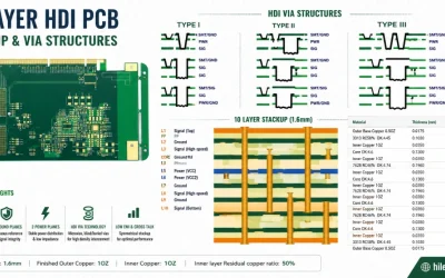
10 Layer HDI PCB Engineering for Microvias and BGA Escape
10 layer HDI PCB engineering guidance for 1+8+1, 2+6+2 and 3+4+3 buildups, microvia reliability, BGA escape, materials and inspection.
Take a Quick Quote