
SMD Capacitor Sizes: Complete Guide to MLCC, Tantalum, and Electrolytic Packages

Introduction to SMD Capacitor Sizes
Understanding SMD capacitor sizes is fundamental to successful PCB design. The physical dimensions of surface mount capacitors directly impact board density, assembly yield, and electrical performance in high-speed circuits. Selecting incorrect capacitor sizes can lead to reliability issues, increased costs, and manufacturing complications.
This guide covers SMD capacitor size codes, dimensional standards, electrical characteristics, and selection criteria. Proper sizing ensures designs meet both performance and manufacturability requirements across consumer electronics, industrial systems, and automotive applications.
What Are SMD Capacitors?
SMD capacitors are surface mount components designed for automated PCB assembly, including multilayer ceramic capacitors (MLCC), tantalum, and electrolytic types. Modern electronics prefer SMD designs because they enable higher component density, faster assembly, and superior high-frequency performance. Size standards vary by technology—ceramic capacitors use dimensional codes while tantalum and electrolytic types use case code designations.

SMD Capacitor Types
Understanding SMD Capacitor Size Codes
Imperial vs Metric Codes
SMD capacitor sizes use two parallel coding systems. The imperial code (inch-based) is common in North America, while the metric code uses millimeters. Both represent identical physical dimensions expressed differently.
| Imperial Code | Metric Code | Actual Dimensions |
|---|---|---|
| 0201 | 0603 | 0.6 × 0.3 mm |
| 0402 | 1005 | 1.0 × 0.5 mm |
| 0603 | 1608 | 1.6 × 0.8 mm |
| 0805 | 2012 | 2.0 × 1.25 mm |
| 1206 | 3216 | 3.2 × 1.6 mm |
The imperial code represents dimensions in hundredths of an inch—”0603″ indicates 0.06″ × 0.03″. The metric code directly states millimeter dimensions—”1608″ means 1.6 mm × 0.8 mm. Engineers must recognize both systems to avoid procurement and design errors.
Why SMD Capacitor Size Matters Electrically
Physical dimensions significantly affect electrical performance across multiple parameters:
- Voltage capability – Larger packages accommodate thicker dielectrics, enabling higher voltage ratings
- High-frequency response – Smaller sizes offer lower ESL and ESR, improving decoupling effectiveness above 10 MHz
- DC bias sensitivity – 0402 capacitors lose 60-80% capacitance under rated voltage; 0805 packages lose only 30-40%
- Current handling – Larger packages dissipate heat better, supporting higher ripple current specifications
SMD Capacitor Size Chart
Standard SMD MLCC Sizes Chart
Understanding the relationship between SMD capacitor sizes, capacitance values, and voltage ratings enables informed component selection. Standard ceramic capacitor packages follow consistent patterns across manufacturers.
Maximum capacitance in smaller sizes requires high-K dielectrics (X5R, X7R), which exhibit greater DC bias effects. Applications requiring both high capacitance and voltage stability necessitate larger package sizes despite board space constraints.
| Imperial Code | Metric Code (mm) | Dimensions (L × W × H mm) | Typical Capacitance Range | Typical Voltage Rating |
|---|---|---|---|---|
| 01005 | 0402 | 0.4 × 0.2 × 0.2 | 0.1 pF – 100 nF | 4–10 V |
| 0201 | 0603 | 0.6 × 0.3 × 0.3 | 0.1 pF – 0.22 µF | 6.3–16 V |
| 0402 | 1005 | 1.0 × 0.5 × 0.5 | 0.1 pF – 1 µF | 10–25 V |
| 0603 | 1608 | 1.6 × 0.8 × 0.8 | 10 pF – 10 µF | 16–50 V |
| 0805 | 2012 | 2.0 × 1.25 × 1.25 | 100 pF – 22 µF | 25–100 V |
| 1206 | 3216 | 3.2 × 1.6 × 1.6 | 1 nF – 47 µF | 50–200 V |
| 1210 | 3225 | 3.2 × 2.5 × 2.5 | 1 nF – 100 µF | 50–250 V |
| 1812 | 4532 | 4.5 × 3.2 × 2.5 | 10 nF – 100 µF | 100–500 V |
| 2220 | 5650 | 5.7 × 5.0 × 2.5 | 100 nF – 220 µF | up to 1 kV |
1. Larger MLCC sizes typically offer higher voltage ratings and higher capacitance.
2. Smaller MLCCs (0201/0402) suffer more from DC bias effect.
SMD Tantalum Capacitor Sizes Chart
| Case Code | Dimensions (L × W × H mm) | Typical Capacitance Range | Typical Voltage Rating | Common Package Examples |
|---|---|---|---|---|
| A (3216-18) | 3.2 × 1.6 × 1.8 | 0.1 µF – 220 µF | 2.5–35 V | TAJA, TPS-A |
| B (3528-21) | 3.5 × 2.8 × 2.1 | 1 µF – 470 µF | 4–50 V | TAJB, TPS-B |
| C (6032-28) | 6.0 × 3.2 × 2.8 | 2.2 µF – 680 µF | 4–50 V | TAJC, TPS-C |
| D (7343-31) | 7.3 × 4.3 × 3.1 | 10 µF – 1000 µF | 6.3–50 V | TAJD, TPS-D |
| E (7343-43) | 7.3 × 4.3 × 4.3 | 10 µF – 1500 µF | 6.3–63 V | TAJE |
| V (7343-20 Low Profile) | 7.3 × 4.3 × 2.0 | 4.7 µF – 680 µF | 6.3–35 V | Low-profile versions |
1. Tantalum capacitors use case letters, not imperial codes.
2. They offer high capacitance density, but lower surge current capability than MLCC.
SMD Electrolytic Capacitor Sizes Chart (Aluminum SMD)
| Case Diameter × Height (mm) | Typical Capacitance Range | Typical Voltage Rating | Common Applications |
|---|---|---|---|
| 4 × 5.4 | 1 µF – 47 µF | 4–16 V | Low-power DC circuits |
| 5 × 5.4 | 4.7 µF – 100 µF | 6.3–25 V | Consumer electronics |
| 6.3 × 5.4 | 10 µF – 220 µF | 6.3–35 V | General-purpose filtering |
| 6.3 × 7.7 | 22 µF – 330 µF | 10–50 V | Power rails |
| 8 × 10 | 47 µF – 1000 µF | 16–63 V | DC-DC converters |
| 10 × 10 | 100 µF – 1500 µF | 16–100 V | Industrial power systems |
| 10 × 12.5 | 220 µF – 2200 µF | 16–100 V | Automotive, LED drivers |
| 12.5 × 13.5 | 330 µF – 3300 µF | 25–100 V | High-ripple power supplies |
1. Aluminum SMD capacitors follow diameter × height naming, not imperial code.
2. Larger cans = higher ripple current and higher voltage capability.
How to Identify SMD Capacitor Sizes
Visual Measurement Methods
Physical measurement using precision calipers provides direct size identification. Measure both length and width, then match dimensions to standard size codes. PCB footprint dimensions in CAD software also reveal intended component sizes through pad-to-pad spacing and copper patterns.
Reading Manufacturer Codes
Most SMD capacitors lack physical markings due to their small size. Identification relies on:
- Original packaging – Displays complete part numbers and specifications on tape reels
- BOM documentation – Cross-reference assembly files with manufacturer datasheets
- IPC-7351 footprints – Pad dimensions and spacing indicate intended component sizes
- Placement files – Pick-and-place data confirms size codes before assembly
Selecting SMD Capacitor Sizes: Electrical and Mechanical Factors
Electrical Performance Characteristics
Package size directly influences frequency response and current handling. Smaller SMD capacitor sizes like 0402 exhibit 30-50% lower ESL than 0805 packages, making them superior for high-frequency decoupling above 10 MHz. Ripple current capability scales with physical size—larger packages dissipate heat more effectively through terminals and body mass.
Voltage Rating Considerations
Voltage ratings increase with SMD capacitor sizes because larger packages accommodate thicker dielectric layers. Industry best practices recommend operating at 50% of rated voltage for consumer applications and 30% for automotive or industrial use. This derating requirement often necessitates larger sizes than electrical specifications alone would suggest.
Mechanical Reliability Factors
Mechanical stress from board flexure creates different failure modes across capacitor sizes:
- Flex cracking risk – 0805 and larger MLCCs experience greater strain during PCB bending due to increased lever arm length
- Vibration resistance – Smaller sizes withstand shock better due to lower mass and reduced mechanical stress concentration
- Thermal cycling – Larger packages provide thicker terminal connections that better accommodate thermal expansion mismatches
- Handling sensitivity – 0201 and 0402 components require careful processes to prevent damage during assembly

SMD Tantalum Capacitors
PCB Layout Guidelines for SMD Capacitor Sizes
Pad Design Standards
IPC-7351 provides standardized land patterns defining pad dimensions based on component tolerance and density level. Pads typically extend 0.1-0.3 mm beyond component terminations. Smaller SMD capacitor sizes like 0201 and 0402 require tighter tolerances and more precise stencil alignment during assembly.
Strategic Placement
Decoupling capacitors should be placed as close as possible to IC power pins, with 0201 and 0402 sizes providing the most effective high-frequency noise suppression. Minimize via placement and trace routing between capacitors and power pins to reduce parasitic inductance. Avoid placing large ceramic capacitors near board edges or mounting holes where mechanical stress concentrates.
Assembly Process Considerations
Smaller component sizes demand tighter reflow process control. Uneven heating or excessive solder paste causes tombstoning, particularly severe with 0201 and 0402 sizes due to low mass. PCB warpage during reflow can create pad coplanarity issues with larger capacitor sizes—control board thickness, copper distribution, and reflow profile shape to prevent defects.
Common Applications by SMD Capacitor Size
Different SMD capacitor sizes serve specific application needs based on electrical and physical characteristics. Space-constrained consumer electronics favor the smallest sizes meeting voltage and capacitance requirements, while automotive and industrial applications prioritize reliability and thermal performance.
| Package Size | Primary Applications |
|---|---|
| 0201 | RF modules, 5G communications, smartphone processors, high-speed differential signaling |
| 0402 | General purpose decoupling, IoT devices, wearable electronics, compact consumer products |
| 0603 | Microcontroller power rails, LED drivers, USB power delivery, general industrial electronics |
| 0805 | Timing circuits, medium voltage applications, automotive infotainment, power supply filtering |
| 1206 | Industrial motor drives, automotive powertrains, high-voltage switching supplies, outdoor equipment |
How to Select the Right SMD Capacitor Size
Define Electrical Requirements First
Begin by establishing fundamental parameters: required capacitance, maximum operating voltage, frequency response, and ripple current. Consider DC bias effects for ceramic capacitors—effective capacitance decreases significantly under rated voltage in smaller packages. Temperature coefficient and dielectric type also influence size selection.
Verify Commercial Availability
Not all combinations of capacitance, voltage rating, and package size exist. High capacitance values like 22 µF rarely appear in 0402 packages above 6.3V rating. Consult manufacturer parametric tools to verify specifications can be met in the desired size before committing to a design. Standard sizes (0402, 0603, 0805) offer broader supplier options and better availability.
Balance Design Constraints
Multiple factors influence optimal SMD capacitor size selection:
- Board space allocation – Compact wearables push toward 0201/0402; industrial controllers accommodate larger, more robust packages
- Assembly capability – Production equipment and process maturity may restrict minimum component sizes
- Cost optimization – 0402 components often cost 2-3× more than equivalent 0603 sizes; assembly costs also increase with miniaturization
- Reliability requirements – Automotive and industrial applications typically favor 0603-1206 sizes for proven long-term performance

SMD Capacitor Sizes Table
Comparison: Small vs Large SMD Capacitor Sizes
Understanding trade-offs between different SMD capacitor sizes helps engineers make informed design decisions. Neither category is universally superior—application requirements, manufacturing capabilities, and cost targets determine optimal sizing for each design.
| Characteristic | Small Sizes (0201–0402) | Large Sizes (0805–1206) |
|---|---|---|
| Capacitance Range | Limited, typically <1 µF | Wide, up to 100+ µF |
| ESR/ESL | Lower, better for HF decoupling | Higher, but adequate for most applications |
| Voltage Rating | Limited, typically <25V | High, commonly 50-200V |
| DC Bias Effect | Severe capacitance loss | Moderate capacitance loss |
| Mechanical Reliability | Fragile during handling, better vibration resistance | Risk of flex cracking, better thermal cycling |
| Assembly Cost | Higher, requires precision equipment | Lower, standard process capability |
| Component Cost | Premium pricing | Economical for standard values |
Conclusion
Field Observations on SMD Capacitor Size Selection
After years of reviewing thousands of PCB designs at Highleap Electronics, we’ve seen that SMD capacitor size choice is often treated as secondary—yet it directly affects circuit stability and long-term reliability. Cases such as 0402 MLCCs losing more than 70% of their capacitance under DC bias are common, especially in power rails where designers prioritize board space over electrical performance.
Common Issues Related to Undersized or Oversized Capacitors
Undersized capacitors frequently show reduced effective capacitance, higher ESR/ESL, and increased susceptibility to thermal stress. On the other hand, larger packages such as 1206 may experience flex cracking in mechanically stressed environments, especially in automotive and industrial products. These issues often trace back to size selection rather than component quality.
Engineering Considerations for Proper Sizing
Capacitor size should be determined by more than layout constraints. Factors including DC bias behavior, voltage derating, thermal characteristics, mechanical reliability, and assembly capability all influence the final selection. In practice, smaller sizes like 0201 or 0402 perform best in high-frequency nodes, 0603 or 0805 work well for general decoupling, and 1206 or larger fit high-voltage or high-capacitance requirements.
Frequently Asked Questions
Are 0402 and 1005 the same size?
Yes, 0402 (imperial) and 1005 (metric) represent identical dimensions of 1.0 × 0.5 mm. The different codes reflect inch-based versus millimeter-based measurement conventions.
What size MLCC is best for decoupling?
For general purpose decoupling, 0402 and 0603 sizes offer optimal balance of performance, cost, and assembly reliability. High-frequency applications above 100 MHz benefit from 0201 packages due to lower parasitic inductance. Bulk decoupling uses 0805 or 1206 sizes for higher capacitance values.
Why do small MLCCs lose capacitance under DC bias?
Small ceramic capacitors use high-K materials (X5R, X7R) compressed into thin layers. Applied voltage creates high electric field strength that saturates the ferroelectric material, reducing effective permittivity. Smaller packages have thinner dielectrics and therefore higher field strength at equivalent voltage, causing 60-80% capacitance loss in 0402 sizes versus 30-40% in 0805 packages.
Can 0201 MLCCs be hand-soldered?
While technically possible with specialized tools and magnification, hand-soldering 0201 components is impractical for production. These miniature sizes require automated pick-and-place equipment and reflow ovens for reliable assembly.
What SMD capacitor sizes are used in automotive electronics?
Automotive applications predominantly use 0603, 0805, and 1206 sizes. These packages provide adequate voltage ratings (50-200V), mechanical robustness for vibration and thermal cycling, and proven reliability under harsh environmental conditions.

Recommended Posts
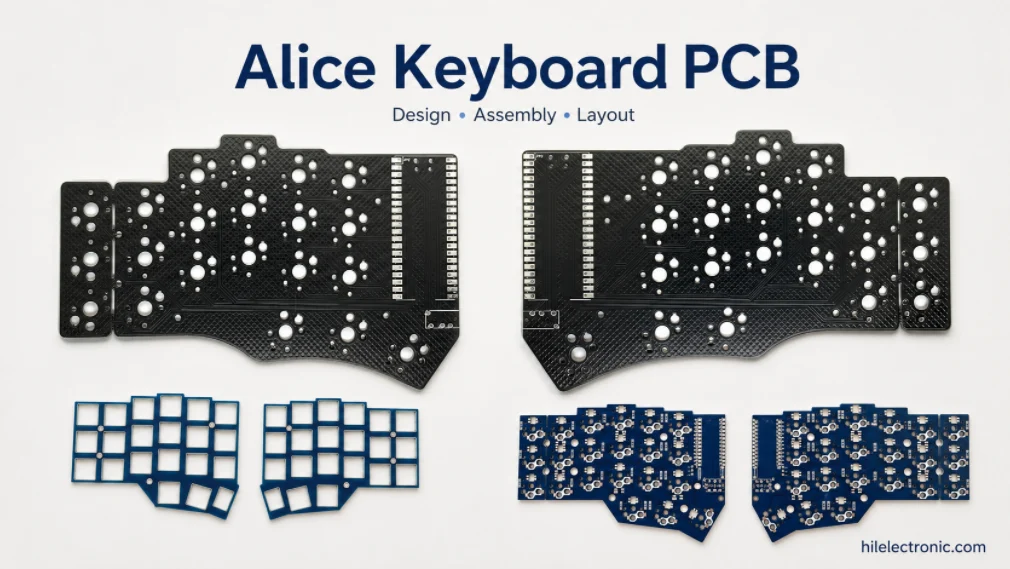
Alice Keyboard PCB Manufacturer | Custom Ergonomic Layout
An Alice keyboard PCB manufacturer must translate an...
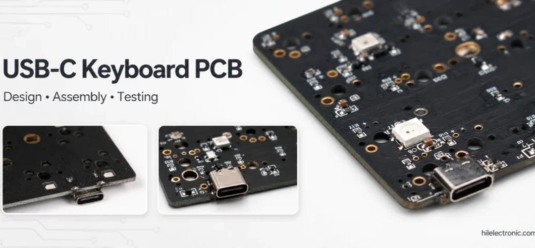
USB-C Keyboard PCB Manufacturer | ESD & Power Protection
A USB-C keyboard PCB manufacturer must control the...

Per-Key RGB Keyboard PCB Manufacturer & LED Assembly
A per-key RGB keyboard PCB manufacturer must control far...

Ortholinear Keyboard PCB Manufacturer | Custom Grid Layout
An ortholinear keyboard PCB manufacturer must preserve a...
How to get a quote for PCBs
Let‘s run DFM/DFA analysis for you and get back to you with a report. You can upload your files securely through our website. We require the following information in order to give you a quote:
-
- Gerber, ODB++, or .pcb, spec.
- BOM list if you require assembly
- Quantity
- Turn time
In addition to PCB manufacturing, we offer a comprehensive range of electronic services, including PCB design, PCBA, and turnkey solutions. Whether you need help with prototyping, design verification, component sourcing, or mass production, we provide end-to-end support to ensure your project’s success.
For PCBA services, please provide your BOM (Bill of Materials) and any specific assembly instructions. We also offer DFM/DFA analysis to optimize your designs for manufacturability and assembly, ensuring a smooth production process.