
Ultra HDI PCB: Advanced Manufacturing for High-Density Applications

Introduction
The electronics industry is pushing toward ever-smaller, higher-performance devices. Smartphones, wearables, and IoT products demand compact form factors while supporting advanced functionality, challenging the limits of conventional HDI PCBs. Ultra HDI (UHDI) PCBs address these needs, enabling ultra-high-density interconnects while maintaining signal integrity and reliability.
Driven by applications such as 5G modules, high-I/O processors, and miniaturized medical devices, UHDI PCBs feature microvias below 50 μm, routing densities over 300 I/O per mm², and complex multilayer stackups unattainable with standard HDI technology.
Ultra HDI PCB: Definition and Technical Characteristics
Key Differentiators from Traditional HDI
Ultra HDI PCBs push beyond conventional HDI capabilities with smaller microvias, higher via density, and advanced layer stacking. Microvia diameters are reduced to below 50 μm, enabling greater interconnect density and freeing routing space. Blind and buried vias often account for over 80% of total vias, minimizing layer transitions and optimizing signal paths. UHDI designs commonly feature 12–20 layers or more, supporting any-layer HDI stackups, with line widths and spacing down to 25 μm, accommodating high-density packages such as flip-chip BGAs and WLCSPs.
| Feature | Ultra HDI PCB | Traditional HDI PCB |
|---|---|---|
| Microvia Diameter | <50 μm | 75–100 μm |
| Blind/Buried Via Ratio | >80% | Typically 40-60% |
| Layer Count | 12-20 layers or more | 4-12 layers |
| Any-Layer HDI Stackup | Widely supported, via can start/end on any layer pair | Limited support |
| Minimum Line Width/Spacing | As low as 25 μm | 50–75 μm |
| Target Component Packages | Advanced Flip-Chip BGA, WLCSP, ultra-high density packages | QFP, standard BGA |
| Interconnect Density | Extremely high | Moderate |
| Routing Efficiency & Space Utilization | Maximized routing space | Standard |
Core Technical Features of UHDI PCB
Ultra HDI PCBs enable extremely compact and high-performance designs by combining ultra-fine features, advanced via technologies, and optimized signal and power routing. Key technical features include:
- Ultra-High Routing Density – Supports routing densities exceeding 300 I/O per mm², with pad-on-via placement maximizing available routing channels.
- Microvia and Via Filling – Laser-drilled microvias filled with copper or conductive pastes ensure mechanical stability and reliable stacked/staggered configurations.
- Signal and Power Integrity – Controlled impedance routing, differential pair matching, strategic ground planes, and optimized PDN minimize crosstalk and maintain clean power delivery.
- Advanced Multilayer Stackups – HDI-on-HDI or coreless constructions enable asymmetric layer buildup, combining ultra-fine outer layers with mechanically robust inner cores.
These features collectively allow UHDI PCBs to support high-density, high-speed components while maintaining manufacturability and reliability.

HDI PCBs
Ultra HDI PCB Design Challenges
Microvia Design Considerations
Designing microvias for Ultra HDI PCBs requires careful attention to geometry, spacing, and via filling methods. Key considerations include:
- Aspect Ratio Limits – Laser-drilled microvias typically maintain an aspect ratio of ≤1:1. For example, a 50 μm via can reliably penetrate no more than 50 μm of dielectric, necessitating sequential buildup and stacked or staggered via configurations.
- Via Spacing – Center-to-center spacing should account for drill tolerances and potential wander, typically ≥100 μm.
- Via Filling Options – Choices include copper-filled, paste-filled, or tented vias:
- Copper-filled: Superior electrical and thermal conductivity but higher process cost.
- Paste-filled or tented: Lower cost, simpler process, but may reduce conductivity or thermal performance.
- Design Trade-offs – Consider electrical current capacity, thermal dissipation, and mechanical reliability when selecting via type and layout.
Effective microvia design balances manufacturability, performance, and cost, ensuring reliable interconnects in high-density UHDI PCB layouts.
High-Density Routing and Impedance Control
Maintaining signal integrity in Ultra HDI PCBs is increasingly challenging due to ultra-fine trace geometries and high routing density. Key considerations include:
- Impedance Control – Narrow line widths (25–40 μm) amplify the effects of etching tolerances, copper weight variations, and dielectric constant inconsistencies. Frequency-dependent dielectric properties and surface roughness must be considered in impedance modeling.
- Crosstalk Mitigation – Use perpendicular routing on adjacent layers, guard traces, or coplanar ground structures for high-speed signals.
- Design Automation – Automated design rule checks (DRC) help ensure compliance with tight electrical and spacing requirements in dense layouts.
Careful planning of trace geometry, layer topology, and automated verification ensures reliable high-speed signal performance in UHDI PCB designs.
Layer Stackup and HDI-on-HDI Architecture
Designing layer stackups for Ultra HDI PCBs requires careful balancing of electrical performance, mechanical reliability, and manufacturability. Key considerations include:
- Thin-Core HDI-on-HDI Structure – Typical cores are 100–200 μm thick with multiple buildup layers on each side, enabling ultra-fine feature routing.
- Copper Balance and Warpage Control – Asymmetric stackups demand precise copper distribution calculations to prevent warpage during reflow and assembly.
- Material Selection – Thin dielectrics must provide consistent electrical insulation and stability across the operating temperature range.
- Sequential Lamination & Tolerance Management – Each lamination cycle introduces tolerance stack-up; via landing pads must be designed with sufficient margin while minimizing wasted routing space.
- Accurate Modeling for Stacked Microvias – Design tools should model accumulated tolerances to ensure reliable interconnections across multiple layers.
Effective UHDI stackup design combines precise material selection, lamination planning, and copper balancing to achieve both high-density routing and mechanical stability.
Thermal Management in UHDI PCB
High component density in Ultra HDI PCBs creates concentrated heat zones, making thermal management a critical design consideration. Key strategies include:
- Optimized Thermal Via Placement – Thermal vias must balance heat dissipation with routing space constraints.
- Material Selection – High-performance laminates such as Rogers, Megtron, or ceramic-filled FR-4 improve thermal conductivity.
- Thermal Simulation – Mandatory simulations identify hotspots and ensure solder joint reliability under thermal cycling.
Effective thermal management ensures UHDI PCBs maintain performance and reliability despite high-density layouts.
Ultra HDI PCB Manufacturing and Process Requirements
Laser Drilling and Microvia Formation
Laser drilling is the foundation of Ultra HDI PCB manufacturing, using CO2 or UV lasers to create sub-50 μm microvias with high precision. Depth control ensures complete dielectric removal without damaging the target pad. Filled vias, either via electroplated copper or conductive paste capped with copper, eliminate voids and enable reliable stacked microvias, directly impacting mechanical and thermal reliability.
Plating and Metallization Processes
Blind and buried via plating requires precise control due to narrow, high-aspect-ratio vias. Specialized chemistries and plating waveforms ensure uniform sidewall coverage, while panel copper thickness is carefully managed. Sequential plating layers demand rigorous quality checks to maintain via integrity and avoid defects that could compromise performance.
Layer Registration and Alignment
Accurate layer-to-layer registration is critical for UHDI PCBs, typically maintained within ±25 μm using optical alignment systems. Misalignment can cause via-to-pad failures in stacked microvias or fine-pitch components. Advanced imaging and intermediate X-ray inspections catch errors early, reducing scrap and improving yield in complex multilayer constructions.
Surface Finish Selection for UHDI PCB
Surface finishes impact assembly reliability and long-term performance. ENIG offers a flat, fine-pitch-compatible surface, while OSP provides a cost-effective option for standard applications. Immersion silver and tin balance cost and performance. For ultra-fine-pitch designs below 0.4 mm, ENIG is usually preferred due to superior planarity.
Quality Control and Reliability Testing
Comprehensive QC includes AOI for surface features, X-ray for buried vias, and flying probe tests for electrical continuity. Reliability screening involves thermal cycling (500–1000 cycles) and, when required, vibration, shock, and environmental stress testing to ensure consistent performance under operating conditions.

Ultra HDI PCBs
Ultra HDI PCB Application Domains
Mobile Devices
Flagship smartphones use UHDI PCBs to integrate advanced processors, memory, multiple cameras, and RF modules in thin form factors. Boards typically feature 8–12 layers with any-layer HDI structures, enabling the high component density required for modern smartphone functionality. Wearables, such as smartwatches, further push miniaturization, fitting full computing systems onto boards smaller than 500 mm².
5G Infrastructure
UHDI PCBs support base stations and small cell modules, handling high-frequency signals with minimal loss. Compact designs integrate power amplifiers, filters, and antennas while maintaining signal integrity at millimeter-wave frequencies. Precise impedance control and minimized via stubs are critical for reliable 5G wireless performance.
Medical Electronics
Implantable devices and portable diagnostic equipment increasingly adopt UHDI PCBs for miniaturization, biocompatibility, and long-term reliability. Cardiac monitors, neurostimulators, and continuous glucose monitors benefit from compact designs while meeting strict quality and performance standards.
Aerospace and Defense
Avionics, radar systems, and satellite communications leverage UHDI PCBs for high reliability and performance. Miniaturization reduces weight in aerospace applications, while defense systems gain the ability to integrate complex functions in ruggedized packages capable of withstanding extreme environments.
Ultra HDI PCB: Advantages and Practical Limitations
Key Advantages of UHDI Technology
Ultra HDI PCBs offer significant benefits for high-performance and compact electronics by enabling ultra-dense routing, improved electrical performance, and product miniaturization. Key advantages include:
- Unmatched Routing Density – Microvias, fine-line traces, and multilayer stackups support extremely high I/O densities, allowing high-pin-count BGAs (sub-0.4 mm pitch) without complex fanout or extra layers.
- Superior Electrical Performance – Short interconnect paths and minimal via stubs reduce signal delay and reflections, improving high-speed digital and RF performance while lowering power consumption.
- Miniaturization and Weight Reduction – Higher routing efficiency decreases layer count, board thickness, and weight, enabling smaller, lighter products for mobile and portable applications.
These advantages make UHDI technology ideal for next-generation devices requiring compact form factors, high-speed operation, and reliable signal integrity.
Practical Limitations and Considerations
While Ultra HDI PCBs provide unmatched performance and miniaturization, several practical limitations must be considered:
-
Higher Cost – Specialized equipment, sequential buildup processes, and premium laminates increase manufacturing expenses, limiting UHDI adoption to applications where performance or miniaturization justifies the cost.
-
Manufacturing Complexity – Multiple lamination cycles, fine features, and tight tolerances create yield challenges, longer lead times, and require advanced process control and inspection.
-
Design Complexity – High-speed design rules, advanced stackup strategies, and precise EDA modeling demand experienced engineers, leading to longer design iteration cycles compared to conventional HDI.
Understanding these constraints helps engineers balance performance benefits with cost, manufacturability, and design feasibility when adopting UHDI technology.
Conclusion: The Future of Ultra HDI PCB Technology
Ultra HDI PCBs are essential for next-generation electronics, enabling high I/O counts and fine-pitch interconnects for advanced components. Ongoing developments in materials, processes, and design methodologies continue to expand what is achievable in circuit board fabrication.
Successful UHDI implementation requires a holistic approach that balances design expertise, material selection, and manufacturing capability. Optimized layouts ensure high performance while maintaining acceptable yield, supported by advanced laminates and precise fabrication processes.
For organizations adopting UHDI technology, choosing the right manufacturing partner is critical. At Highleap Electronics, our dedicated UHDI lines, advanced laser drilling, and experienced engineering team guide designs from concept to production, ensuring reliable, high-performance boards. Contact our team to explore how UHDI PCBs can support your next product.

Recommended Posts
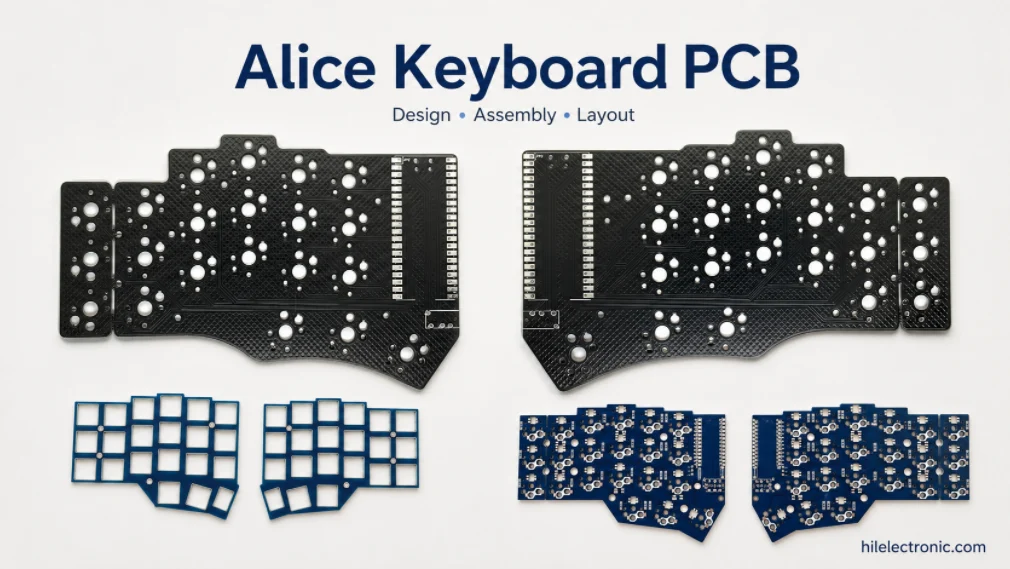
Alice Keyboard PCB Manufacturer | Custom Ergonomic Layout
An Alice keyboard PCB manufacturer must translate an...
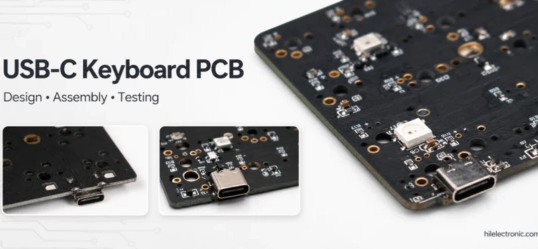
USB-C Keyboard PCB Manufacturer | ESD & Power Protection
A USB-C keyboard PCB manufacturer must control the...

Per-Key RGB Keyboard PCB Manufacturer & LED Assembly
A per-key RGB keyboard PCB manufacturer must control far...

Ortholinear Keyboard PCB Manufacturer | Custom Grid Layout
An ortholinear keyboard PCB manufacturer must preserve a...
How to get a quote for PCBs
Let‘s run DFM/DFA analysis for you and get back to you with a report. You can upload your files securely through our website. We require the following information in order to give you a quote:
-
- Gerber, ODB++, or .pcb, spec.
- BOM list if you require assembly
- Quantity
- Turn time
In addition to PCB manufacturing, we offer a comprehensive range of electronic services, including PCB design, PCBA, and turnkey solutions. Whether you need help with prototyping, design verification, component sourcing, or mass production, we provide end-to-end support to ensure your project’s success.
For PCBA services, please provide your BOM (Bill of Materials) and any specific assembly instructions. We also offer DFM/DFA analysis to optimize your designs for manufacturability and assembly, ensuring a smooth production process.