
Black Box PCB Reverse Engineering for Undocumented Boards

Figure 1. Black box PCB reverse engineering
Table of Contents
- What Defines a Black Box PCB and Why Standard Methods Fall Short
- The Black Box Assessment: Determining What You Are Dealing With
- External Interface Analysis: Working from the Outside In
- Internal Analysis: Defeating Obfuscation and Anti-Tamper Measures
- Behavioral Characterization Without Internal Access
- Reconstructing the Design from Combined Evidence
- Highleap’s Black Box Reverse Engineering Services
Black box PCB reverse engineering addresses the most challenging category of reverse engineering projects: boards where not only is no documentation available, but the board itself has been deliberately designed to resist analysis. Components may have their markings sanded off. The board may be encapsulated in opaque potting compound. Custom ASICs or programmed FPGAs may implement proprietary logic that cannot be identified from external markings. The circuit may be buried inside a sealed enclosure with tamper-detection mechanisms. These are not theoretical obstacles. Military electronics, proprietary industrial controllers, medical device boards, and high-value commercial products routinely employ anti-reverse-engineering measures to protect intellectual property and maintain competitive advantage. When these systems require maintenance, repair, or replacement and the original manufacturer is unavailable, black box reverse engineering is the only path forward. This guide covers the specialized methodology for analyzing fully undocumented systems where the board actively resists standard reverse engineering techniques — from external interface analysis through anti-tamper countermeasures to design reconstruction.
1. What Defines a Black Box PCB and Why Standard Methods Fall Short
1.1 Black Box Characteristics
A black box board differs from a standard undocumented board in one critical respect: information has been deliberately concealed. Standard undocumented boards simply lack documentation due to loss or negligence — all information is accessible on the physical hardware if you know how to extract it. Black box boards have been engineered to prevent or impede that extraction. Common obfuscation techniques:
- Component marking removal: IC markings sanded, laser-ablated, or chemically removed. Without markings, the IC cannot be identified through normal means — the engineer faces an unknown device with unknown pinout and unknown function
- Potting and encapsulation: The entire board (or critical sections) encased in opaque epoxy, urethane, or silicone compound. Components, traces, and even the board substrate are invisible and physically inaccessible
- Custom silicon: Proprietary ASICs or mask-programmed devices that implement the core logic. No datasheet exists because the device was never commercially sold
- Code-protected microcontrollers: Firmware locked behind read protection fuses. The program that defines the device’s behavior cannot be extracted
- Anti-tamper mechanisms: Circuits that detect physical intrusion (lid switches, mesh sensors, voltage monitors) and respond by erasing volatile keys or triggering destructive mechanisms
- Obfuscated PCB layout: Deliberate routing complexity — unnecessary vias, misleading traces, dummy components — designed to increase analysis time and error probability
1.2 Why Standard RE Methods Fail
Standard reverse engineering assumes that component identification is straightforward (read the markings), trace following is a measurement task (image and trace), and circuit function follows from component identity (look up the datasheet). Black box boards break all three assumptions: components cannot be identified by markings, traces may be invisible under potting, and custom silicon has no publicly available datasheet.
2. The Black Box Assessment: Determining What You Are Dealing With
2.1 External Examination
Before attempting to open or analyze the device:
- Photograph all external features: Enclosure markings, labels, regulatory certifications (FCC ID, CE marks, UL listings). FCC IDs can be searched in the FCC database to find internal photographs and test reports that may reveal board details
- Document all connectors: Connector types, pin counts, and any labeling. These define the board’s external interfaces and provide the starting point for behavioral analysis
- Assess encapsulation level: Is the board in a standard enclosure (removable lid)? Sealed enclosure (adhesive or welded)? Potted module (board embedded in compound)?
2.2 Non-Invasive Imaging
| Method | What It Reveals Through Potting | Limitations |
|---|---|---|
| 2D X-ray | Component outlines, IC die size, pin patterns, via locations, trace routing on outer layers | Overlapping layers create ambiguity; potting material may attenuate X-rays |
| CT scanning | Full 3D reconstruction of board, components, and traces — even through potting compound | Resolution limited by potting density; metal-filled potting creates artifacts |
| Acoustic microscopy | Internal layer interfaces, delamination, void detection within potting | Limited penetration depth; requires coupling medium |
CT scanning is the most powerful tool for black box analysis — it can image the board structure, component positions, and even trace routing through potting compound without physical contact. For high-value black box projects, CT scanning should be performed before any physical intervention.
2.3 Risk Assessment
Before proceeding to invasive analysis, assess:
- Is there a tamper-detection mechanism? (Battery-backed volatile memory, mesh sensors, lid switches — visible on CT scan)
- How many sample units are available? (Black box analysis may destroy the sample; having multiple units is strongly preferred)
- What is the acceptable risk level? (Is the goal to understand the circuit, or to produce a functional copy? The former tolerates more analytical damage)

Figure 2. Black Box PCB for reverse engineering — macro view showing encapsulated IC and surrounding components.
3. External Interface Analysis: Working from the Outside In
3.1 Connector Pinout Mapping
Without opening the device, map every connector’s pinout through electrical probing:
- Power pins: Identified by resistance to ground (low resistance = power ground; low resistance to other pins through decoupling = power supply)
- Communication pins: Connect a logic analyzer or oscilloscope and observe signal activity during normal operation. UART signals show characteristic start/stop bit patterns; SPI shows clock + data; I2C shows clock + bidirectional data with ACK/NACK; CAN shows differential signaling
- Analog pins: Measure DC voltage and observe for signal variation. Analog inputs/outputs typically show slowly varying or sensor-correlated signals
- Digital I/O: Observe state changes correlated with device behavior (inputs that change when buttons are pressed; outputs that change when actuators activate)
3.2 Protocol Identification and Decoding
For each communication interface identified:
- Determine the protocol (baud rate, data format, framing)
- Capture and decode the data stream during normal operation
- Identify command/response patterns, data structures, and timing relationships
- Build a protocol specification that describes how the black box communicates with external systems
This external behavioral analysis provides the functional specification that any replacement design must satisfy — even if the internal implementation remains partially unknown.
3.3 Power Analysis
Measure the device’s power consumption profile over time:
- Steady-state power consumption indicates the circuit’s overall complexity
- Power consumption changes correlated with operational states reveal internal activity patterns
- Power-on sequence (inrush current, startup time, initialization current profile) provides clues about internal architecture (processor boot, FPGA configuration, analog calibration)
4. Internal Analysis: Defeating Obfuscation and Anti-Tamper Measures
This section covers the specialized techniques required when standard component identification and trace analysis are blocked by deliberate countermeasures.
4.1 Potting Compound Removal
Removal technique depends on the compound type:
- Silicone potting: Soft; carefully cut and peel. Lowest risk to components. Often used when the primary goal is environmental protection rather than IP concealment
- Urethane potting: Medium hardness. Chemical dissolution (proprietary solvents) or careful mechanical milling. Moderate component damage risk
- Epoxy potting: Very hard. Requires CNC micro-milling guided by CT scan data to remove material without contacting components. High risk — components may be damaged during removal. CT scan data is used to program milling depth limits above each component
- Metal-filled epoxy: Some high-security applications use epoxy loaded with metalite particles to block X-ray imaging. These require specialized removal techniques and significantly more analysis time
4.2 Identifying Components with Removed Markings
When IC markings have been sanded or ablated:
- Package analysis: The IC package type (QFP, BGA, SOIC, QFN) and pin count narrow the candidate range significantly. An 8-pin SOIC with specific power pin locations is likely a voltage regulator, op-amp, or small memory device
- Circuit context: The components connected to the unknown IC provide strong identification clues. An IC connected to a crystal oscillator, SPI flash, and multiple GPIO-connected peripherals is almost certainly a microcontroller
- Die examination (decapsulation): Chemical or mechanical removal of the IC package material exposes the silicon die. Die markings (often present even when package markings are removed), die size, and bond pad layout can identify the device
- Infrared imaging under operation: Thermal emission patterns from powered ICs reveal internal die structure and operating sections, providing clues about device type and function
4.3 Handling Custom ASICs
If the black box contains a custom ASIC (application-specific integrated circuit), it cannot be identified from any database because it was never commercially sold. Approaches:
- Functional characterization: Map all I/O behavior by stimulating inputs and observing outputs. Build a behavioral model that describes what the ASIC does without knowing how
- FPGA emulation: Implement the characterized behavior in a modern FPGA as a functional replacement for the unknown ASIC. This does not replicate the ASIC’s internal design but produces equivalent external behavior
- Die reverse engineering: For the most extreme cases, the ASIC die can be photographed layer by layer and the gate-level circuit reconstructed from the images. This is extremely expensive ($50,000–$500,000+) and typically reserved for military or national-security applications

Figure 3. Black Box PCB Reverse Engineering Process
5. Behavioral Characterization Without Internal Access
5.1 When Physical Analysis Is Not Possible
In some cases, the black box cannot be opened (destructive tamper mechanisms, single irreplaceable sample, or regulatory restrictions). The entire reverse engineering effort must rely on external behavioral analysis:
- Comprehensive I/O mapping and protocol decoding (as described in Section 3)
- Transfer function characterization: for each input/output relationship, measure the mathematical function that transforms input to output across the operating range
- Timing characterization: measure all response times, latencies, and periodic behaviors
- State machine analysis: identify the device’s operating states, transitions, and transition conditions
5.2 Building a Functional Replacement from Behavioral Data
A behavioral specification enables the design of a functional replacement without knowing the internal implementation:
- Select a processor or FPGA platform capable of implementing the required I/O interfaces and processing speed
- Implement the characterized transfer functions, state machine, and timing in firmware or HDL
- Design the board with identical connector positions and pinout for drop-in compatibility
- Validate against the original device through side-by-side comparison testing
This approach produces a board that behaves identically to the original from the system’s perspective — even though the internal implementation may be completely different.
6. Reconstructing the Design from Combined Evidence
6.1 Evidence Fusion
Black box reverse engineering rarely relies on a single analysis technique. Instead, evidence from multiple sources is combined:
- CT scan data provides component positions and board structure
- External behavioral analysis provides functional specifications
- Potting removal (if performed) provides component markings and trace access
- IC decapsulation provides device identification for unmarked components
- Protocol decoding provides communication interface specifications
Each evidence source fills gaps left by the others. The reconstruction is complete when all evidence sources converge on a single, consistent design description.
6.2 Deliverables from Black Box Projects
Depending on the analysis depth achieved:
- Full reconstruction: If potting was removed and all components identified — standard deliverables (schematic, Gerber, BOM, netlist) equivalent to a normal RE project
- Functional replacement design: If full physical analysis was not possible — a new board design that replicates the original’s external behavior using modern components. Includes new schematic, new Gerber, new BOM, and behavioral validation report
- Interface specification: If only external analysis was performed — comprehensive documentation of all interfaces, protocols, timing, and transfer functions. Sufficient for designing a replacement system that interacts correctly with the black box’s host equipment
7. Highleap’s Black Box Reverse Engineering Services
Highleap Electronics provides specialized black box analysis for the most challenging reverse engineering projects:
- Advanced imaging: CT scanning through potting compound, X-ray analysis of encapsulated assemblies, and die-level photography for unmarked ICs
- Potting removal: CNC micro-milling guided by CT data, chemical dissolution, and mechanical decapsulation — with component preservation protocols
- Behavioral analysis: Protocol decoding, transfer function characterization, and state machine analysis for devices that cannot be opened
- FPGA emulation: Custom ASIC functionality replicated in modern FPGA platforms for functional replacement
- Complete deliverables: Full schematic reconstruction where physical analysis permits; behavioral replacement design where it does not
- Manufacturing integration: From analysis through prototype fabrication, assembly, and functional validation
- Strict NDA: Black box projects demand the highest confidentiality — our security protocols match

Recommended Posts

Pilot Run PCB Assembly for Production Validation
Table of contents What a PCB Assembly Pilot Run Should...

Contract Manufacturing Transfer Without PCBA Supply Disruption
Table of contents Why PCB Assembly Transfers Fail The...
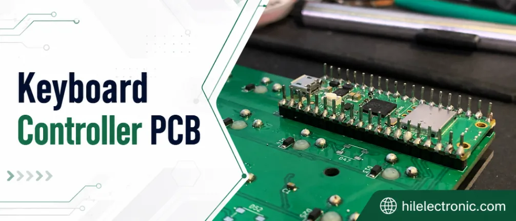
Keyboard Controller PCB Manufacturer | MCU Programming
A keyboard controller PCB manufacturer must deliver a...

Industrial Keyboard PCB Manufacturer | Durable Control Panels
An industrial keyboard PCB manufacturer must design the...
How to get a quote for PCBs
Let‘s run DFM/DFA analysis for you and get back to you with a report. You can upload your files securely through our website. We require the following information in order to give you a quote:
-
- Gerber, ODB++, or .pcb, spec.
- BOM list if you require assembly
- Quantity
- Turn time
In addition to PCB manufacturing, we offer a comprehensive range of electronic services, including PCB design, PCBA, and turnkey solutions. Whether you need help with prototyping, design verification, component sourcing, or mass production, we provide end-to-end support to ensure your project’s success.
For PCBA services, please provide your BOM (Bill of Materials) and any specific assembly instructions. We also offer DFM/DFA analysis to optimize your designs for manufacturability and assembly, ensuring a smooth production process.