
Capacitor Types — How to Choose the Right Capacitor for Your PCB Design

Introduction
Selecting appropriate capacitor types demands balancing electrical performance, environmental constraints, physical dimensions, and supply chain factors. Electrical parameters including capacitance, voltage rating, ESR, and ripple current must align with application requirements. Environmental conditions affect reliability while mechanical constraints influence form factor decisions. This guide provides systematic selection criteria, application-specific recommendations, and design verification methods for PCB assembly projects.
Capacitor Selection Framework: Key Decision Factors
The capacitor selection process begins with defining primary application requirements.
- Decoupling and bypass applications – Prioritize low inductance and high-frequency response for stable power integrity.
- Bulk energy storage – Require high capacitance density with sufficient ripple-current tolerance.
- Timing and filtering circuits – Depend on capacitors with stable temperature coefficients and low drift.
- Safety applications on AC line inputs – Mandate certified X/Y-rated components that meet regulatory standards.
Critical Selection Parameters
Establishing voltage and capacitance requirements defines the initial parameter space. Derating guidelines recommend operating at 50-70% of rated voltage for improved reliability. Frequency response targets favor ceramic capacitors for high-frequency decoupling above 1 MHz. The following factors complete the decision matrix:
- ESR and ripple current specifications – Critical for switching power supply outputs where thermal management directly affects lifespan
- Volume efficiency versus reliability trade-offs – Distinguishes polymer and tantalum options from aluminum electrolytic alternatives
- Cost and procurement factors – Including lead times, second-source availability, and lifecycle status
- Environmental operating conditions – Temperature range, humidity, and mechanical stress requirements
Together, these factors ensure that capacitor selection aligns with real-world performance, reliability, and manufacturing expectations.
Technical Comparison of Capacitor Types
MLCC and Ceramic Capacitors
- Advantages – Multi-layer ceramic capacitors (MLCCs) offer compact size and low equivalent series inductance (ESL), making them ideal for high-frequency decoupling. Class I dielectrics (C0G/NP0) ensure tight tolerance and temperature stability, while Class II (X7R, X5R) provide higher capacitance in a smaller footprint.
- Limitations – DC-bias effects can reduce effective capacitance by 50–80% in high-K dielectrics, and small case sizes with high nominal ratings are particularly affected.
- Design considerations – Evaluate capacitance at actual operating voltage rather than zero-bias specifications, choose temperature coefficients based on tolerance requirements (C0G ±30 ppm/°C, X7R ±15%), and consider parallel combinations of different case sizes to optimize frequency response.

Aluminum Electrolytic Capacitors
- Advantages – Aluminum electrolytic capacitors offer high capacitance at low cost, making them suitable for bulk energy storage and low-frequency filtering in power supplies. Modern low-ESR and solid polymer types improve ripple current handling and high-frequency performance compared to traditional wet electrolytics.
- Limitations – Lifespan is highly temperature-dependent, with each 10°C rise roughly halving operating life. ESR and ripple current limits must be carefully observed to avoid overheating and premature failure.
- Design considerations – Verify ripple current against actual circuit conditions, consider parallel combinations with ceramic capacitors to extend frequency response, and account for mounting orientation and proximity to heat sources to maintain reliability in high-temperature environments.

Tantalum and Polymer Tantalum Capacitors
- Advantages – Tantalum capacitors offer high volumetric efficiency and stable electrical performance across temperature and frequency ranges. Polymer tantalum types achieve ESR below 10 mΩ, rivaling ceramics while maintaining high capacitance density, making them ideal for space-constrained designs and voltage regulator outputs.
- Limitations – Traditional MnO₂ tantalum capacitors are sensitive to voltage transients and inrush currents, requiring careful surge protection and derating to ~50% of rated voltage. Cost is higher than aluminum electrolytics, and supply chain concentration requires sourcing attention.
- Design considerations – Use polymer tantalum to eliminate ignition failure risks and achieve lower ESR. Ensure voltage derating for MnO₂ types, and select capacitance and packaging to optimize performance in high-density or high-frequency applications.

Film Capacitors
- Advantages – Film capacitors using polypropylene, polyester, or polyphenylene sulfide dielectrics provide excellent linearity, low loss, and stable performance, making them ideal for precision analog, audio, and high-voltage applications. Metallized film types offer self-healing properties that enhance reliability.
- Limitations – Larger physical size compared to ceramic or electrolytic capacitors limits use in space-constrained designs. They may also be less suitable for very high capacitance requirements in compact boards.
- Design considerations – Choose dielectric type based on voltage, frequency, and temperature requirements. Leverage self-healing metallized constructions for AC or high-voltage DC filtering, and account for board space when integrating into resonant circuits, snubbers, or EMI filters.

Safety Capacitors for AC Line Applications
- Advantages – Class X and Y safety capacitors provide effective EMI suppression on AC mains inputs while complying with stringent safety standards. X capacitors connect line-to-line, and Y capacitors connect line-to-ground, ensuring reliable protection and regulatory compliance.
- Limitations – Safety capacitors require strict placement, creepage, and clearance rules. Improper layout or substitution with standard capacitors can lead to regulatory violations and safety hazards.
- Design considerations – Select capacitors according to certification requirements (UL, VDE, ENEC), include discharge resistors for X types, and maintain proper isolation barriers and spacing on the PCB. Balance EMI filtering performance with allowable leakage currents for Y types.

Critical Electrical Parameters for Capacitor Selection
ESR and Ripple Current in Power Applications
Equivalent series resistance directly determines power dissipation and thermal performance in high-current applications. Switching power supply output capacitors experience continuous ripple current generating I²R losses that must remain within thermal limits. Low-ESR polymer and specialized aluminum electrolytic types provide superior ripple current handling for buck converter outputs and high-current regulator applications.
DC Bias and Temperature Stability
Ceramic capacitor selection requires careful attention to DC-bias characteristics where applied voltage reduces effective capacitance well below nominal ratings. High-K dielectric formulations (X7R, X5R) exhibit pronounced voltage sensitivity with capacitance declining 30-80% at rated voltage. Circuit designers must specify sufficient nominal capacitance to achieve required effective values under operating conditions, typically requiring 2-3× overhead for X7R types.

Voltage Rating and Derating Guidelines
Voltage derating extends operational lifetime across all capacitor technologies. Industry practice recommends 50% derating for ceramic types and 70% for electrolytic constructions in commercial applications. Transient voltage conditions including inrush, switching spikes, and fault scenarios must remain within absolute maximum ratings. AC-rated capacitors for safety applications require specific certifications that consider peak voltages and isolation requirements beyond basic electrical specifications.
Application-Specific Capacitor Selection Guide
High-Speed Digital Decoupling and Power Integrity
Power distribution network design for high-speed digital circuits employs multiple ceramic capacitor values in parallel configurations. Target impedance specifications typically require 0.1 μF and 1 μF ceramic capacitors placed immediately adjacent to integrated circuit power pins. Different case sizes provide staggered self-resonant frequencies creating broadband impedance reduction from DC through several hundred megahertz. DC-bias effects necessitate choosing capacitors with sufficient nominal ratings to achieve required effective capacitance at operating voltage.
Switching Power Supply Output Filtering
Output capacitor selection for DC-DC converters balances ESR requirements, ripple current capability, and bulk capacitance needs. Low-ESR polymer aluminum or specialized electrolytic types provide excellent ripple current handling with controlled ESR values that influence stability and transient response. Total output capacitance derives from load transient response requirements and allowable voltage deviation specifications. ESR contributes directly to output ripple voltage through V_ripple = I_ripple × ESR relationship.
Analog and Audio Signal Path Filtering
Film capacitors provide superior linearity and low-distortion characteristics for precision analog and audio signal filtering. Polypropylene types excel in audio coupling and crossover networks where dielectric absorption and voltage coefficients directly impact sound quality. Active filter implementations benefit from film capacitor stability and predictable aging characteristics. Precision timing circuits similarly favor film or C0G ceramic options where long-term drift affects circuit accuracy.
High-Power Bulk Energy Storage
Motor drive inverters and high-power DC filtering applications require large capacitance values where aluminum electrolytic capacitors provide optimal cost per microfarad. Ripple current capability becomes the primary selection criterion with thermal management directly affecting lifetime in high-ambient-temperature installations. Parallel configurations distribute current and improve reliability while providing redundancy against single-point failures.
Common Capacitor Selection Mistakes
Ignoring DC-Bias Effects in MLCC Types
Nominal capacitance values do not represent effective capacitance in operation, particularly for ceramic capacitors under DC bias conditions. Designers frequently underestimate capacitance reduction in X7R types, requiring 2-3× nominal values to achieve target effective capacitance at rated voltage. This oversight leads to inadequate decoupling and power integrity issues in high-speed digital designs.
Overlooking ESR and Ripple Current Ratings
Insufficient attention to ESR and ripple current specifications results in thermal failures and reduced reliability in power supply applications. Capacitors operating beyond ripple current ratings experience accelerated aging despite adequate capacitance values. Temperature effects compound these issues where elevated ambient conditions reduce both ripple current capability and expected lifetime.
Engineering Checklist for Capacitor Types Selection
Systematic evaluation ensures appropriate capacitor selection for specific applications. The following checklist addresses critical parameters:
- Application category – Decoupling, bulk storage, timing, filtering, or safety functions with corresponding performance priorities
- Voltage requirements – Actual operating conditions with appropriate derating margins verified against worst-case transients
- Effective capacitance – DC-bias curves for ceramic types ensuring effective capacitance at operating voltage meets circuit requirements
- Thermal specifications – ESR and ripple current ratings satisfy power dissipation constraints within temperature limits
- Environmental factors – Operating temperature range, mechanical mounting reliability, and lifecycle requirements
Professional Insights on Capacitor Selection
Key Considerations
Successful capacitor selection depends on understanding DC-bias effects, thermal management, and application-specific requirements. Treating nominal datasheet specifications as guaranteed operating values—especially for ceramics—often leads to design issues due to voltage-induced capacitance loss.
Evaluation Beyond Datasheets
Robust designs require analyzing DC-bias curves, ripple current derating, and temperature-dependent ESR rather than relying solely on capacitance and voltage ratings. The cost of optimal capacitor choice is usually minimal compared to redesigns or field failures.
Technology-Specific Roles
Different capacitor types serve distinct purposes: MLCCs excel in high-frequency decoupling, aluminum electrolytics provide cost-effective bulk storage, tantalums offer high volumetric efficiency, and film capacitors ensure precision performance. Understanding these differences allows engineers to balance performance, reliability, and design constraints effectively.

Recommended Posts
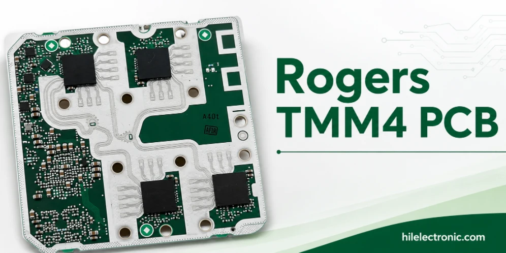
Rogers TMM4 PCB Manufacturer for Compact Microwave Filters
TMM4 is most useful when a microwave circuit must become...
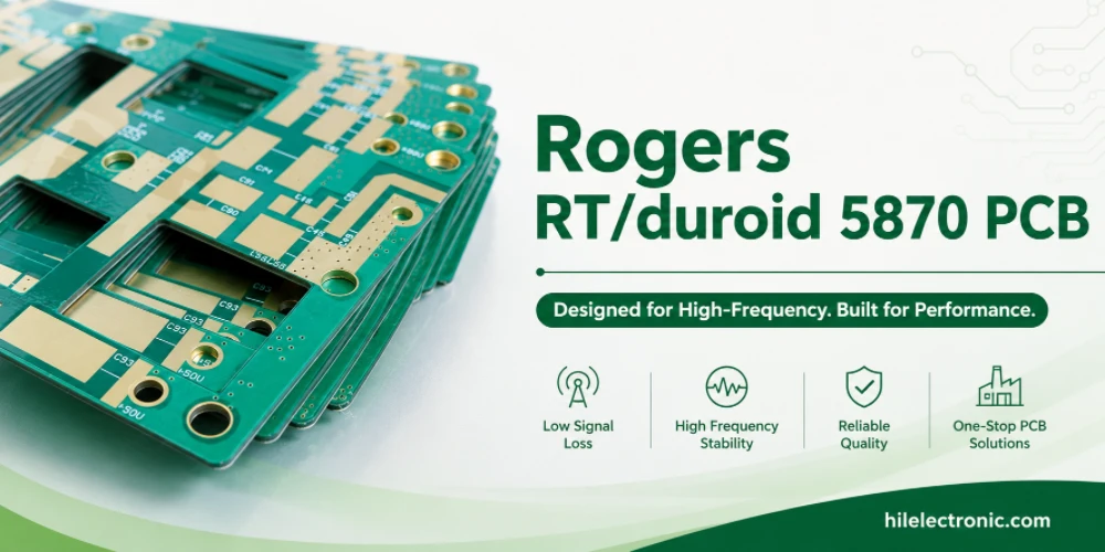
RT/duroid 5870 PCB Manufacturer for Low-Loss PTFE RF Circuits
RT/duroid 5870 is chosen when the RF path needs low loss,...
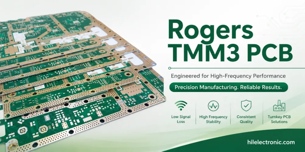
Rogers TMM3 PCB Manufacturer for Mechanical RF Modules
TMM3 is selected when an RF circuit must behave as part of...
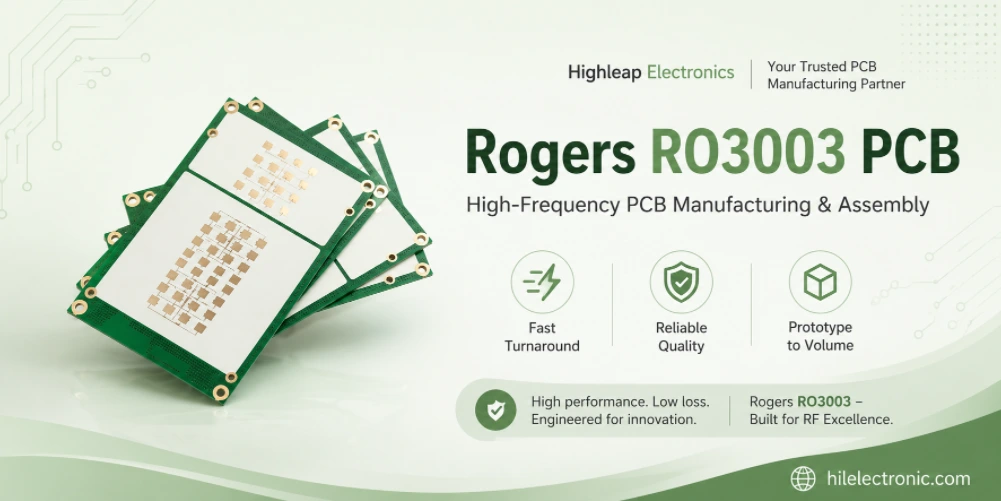
Rogers RO3003 PCB Manufacturer for Automotive Radar and mmWave Modules
A 77 GHz radar board is purchased as a working sensor...
How to get a quote for PCBs
Let‘s run DFM/DFA analysis for you and get back to you with a report. You can upload your files securely through our website. We require the following information in order to give you a quote:
-
- Gerber, ODB++, or .pcb, spec.
- BOM list if you require assembly
- Quantity
- Turn time
In addition to PCB manufacturing, we offer a comprehensive range of electronic services, including PCB design, PCBA, and turnkey solutions. Whether you need help with prototyping, design verification, component sourcing, or mass production, we provide end-to-end support to ensure your project’s success.
For PCBA services, please provide your BOM (Bill of Materials) and any specific assembly instructions. We also offer DFM/DFA analysis to optimize your designs for manufacturability and assembly, ensuring a smooth production process.