
Back to blog
Top 6 Things to Know about Circuit Card Assembly

Circuit Card Assembly
The process of learning about circuits and how to assemble them is quite straightforward, making this guide immensely helpful for beginners. We will delve into the basics of electricity and its relationship to circuits, as well as touch on the materials necessary for circuit assembly. This foundational knowledge will provide you with a solid understanding as you progress to more advanced concepts.
What is Circuit Card Assembly?
Circuit card assembly involves several stages. Circuit card assemblies are complete PCBs after the assembly of every component. A printed circuit board does not have any electrical components, whereas circuit card assemblies are complete board assemblies. Assembling a circuit board requires both active and passive components.
Circuit card assembly is also known as printed circuit board assembly, with these terms widely used in the PCB industry. The process of circuit card assembly involves several stages, including using schematic capture tools or CAD software. It involves connecting the wiring of PCBs with electronic components, with the traces in the copper sheets of PCBs forming the assembly.
Ways to Create Circuit Card Assemblies
There are several ways to create circuit assemblies, each requiring attention to detail.
Plated Through-Hole Technology (PTH): This method involves mounting components on the circuit board by inserting their leads through the respective hole. The circuit board is pre-drilled, making it easy to assemble the components. A thin layer of copper covers the inner wall of the holes, making the entire inner hole area conductive.
Surface Mount Technology (SMT): This is a common method for creating card assemblies, preferred in the PCB industry. SMT involves using automated machines to assemble electronic components on a circuit board.
Electro-Mechanical Assembly: This method uses cable assembly, molded plastics, wire harnesses, and looms to assemble electronic components on a PCB, ensuring the smooth function of electronic devices.
Steps in Circuit Card Assembly
Printed circuit boards form the backbone of most electronic devices, providing connectivity for their components. A circuit card assembler ensures that the circuit board is properly assembled, following a step-by-step process. However, these steps may vary based on the method of PCB assembly.
-
Schematic Design: Design a schematic that serves as a guideline for the entire circuitry. This schematic, a roadmap featuring symbols representing the entire circuit board, helps you tackle any future problems.
-
Board Design Layout: Translate the schematic into design software, then export it into an acceptable format for the production stage of the circuit board.
-
Manufacturing & Assembling the PCB: Create the board using different assembly methods, such as plated through-hole technology or surface mount technology, depending on the board’s specific requirements.
-
Inspection and Testing: Test the circuit board to ensure it functions perfectly, using methods like visual inspection, X-ray inspection, and automatic optical inspection for complex PCBs.

Circuit Card Assembly
Circuit Assembly Design Basics
In circuit assembly, understanding the basics of circuit assembly design is crucial, as all circuit boards feature specific layers:
- Substrate: This is the foundational material providing rigidity to the circuit board. Most circuit boards use fiberglass for their substrate layer. Flexible PCBs may use different materials suited to their flexibility requirements.
- Copper: Printed circuit boards (PCBs) feature a layer of copper foil. Manufacturers laminate the copper foil to the board using heat. The number of copper layers varies based on the type of PCB. For example, single-sided PCBs require copper on only one side of the board, while multilayer PCBs can have multiple layers of copper.
- Solder Mask: The solder mask layer is applied on top of the copper layer. It is typically green or yellow in color and serves to insulate the copper layer, preventing it from coming into contact with other metals on the board. The solder mask also helps manufacturers solder components to the appropriate places on the board.
- Silkscreen: The silkscreen layer is the topmost layer of all circuit boards. It features components in symbolic or textual form, helping engineers understand the functions of various parts of the board. The silkscreen layer adds symbols, letters, and numbers to the board, aiding in assembly and troubleshooting.
Understanding these basic layers of circuit assembly design is essential for anyone working with electronic devices, as it provides insight into how circuit boards are constructed and how they function within electronic devices.
Manufacturing Steps of Circuit Card Assembly
The manufacturing process of circuit card assembly involves several key steps:
Solder Paste Stenciling:
-
- Solder paste is applied to specific areas of the circuit board where components will be mounted.
- A stencil is used to ensure precise application of solder paste to the board.
- Various applicators, such as squeegees or rollers, are used to spread the solder paste evenly on the board.
Pick and Place:
-
- An automated machine, known as a pick-and-place machine, is used to accurately place surface-mount components (SMDs) and other electronic components onto the PCB.
- Components are picked up from reels, trays, or tubes and placed onto the solder paste on the board.
- The machine uses vision systems or mechanical alignment to ensure components are placed accurately.
Reflow Soldering:
-
- After components are placed on the board, the PCB is passed through a reflow oven.
- The reflow oven heats the board to a temperature that melts the solder paste, bonding the components to the board.
- The oven then cools the board, solidifying the solder and securing the components in place.
Quality Control:
-
- After the reflow soldering process, the assembled board undergoes rigorous inspection to ensure it meets quality standards.
- Visual inspection is performed to check for solder defects, component misalignment, or other visible issues.
- Automated optical inspection (AOI) or X-ray inspection may also be used to detect defects that are not visible to the naked eye.
- Functional testing may be performed to verify that the board operates as intended.
These steps are crucial in the manufacturing process of circuit card assembly to ensure that the final product meets quality standards and functions correctly.
Basic Electronic Components Necessary for Circuit Assembly
There are some rudimentary electronic components necessary for assembling electronic circuits, including:
- Resistors: Adding resistance to electric current flowing in a circuit, with different values represented by color codes.
- Diodes: Allowing electric current to flow in one direction, useful for controlling the direction of current flow.
- Transistors: Amplifying electric current, serving as a switch without moving parts, and controlled by a small amount of current at its base pin.
- Potentiometers: Varying resistance using a slider or knob, often used to regulate brightness and volume.
- Integrated Circuit (IC): A miniature form of a large circuit containing millions of tiny transistors and resistors, receiving input and providing output through several terminals.
- Light Emitting Diode (LED): Converting electricity into light, more durable than incandescent light bulbs.
- Switch: Mechanically breaking a circuit, opening or closing it depending on the switch type.
- Battery: Converting chemical energy into electrical energy, containing specific chemicals that react to create electricity.
- Breadboard: Testing and designing circuits without soldering components and wires.
- Multimeter: Measuring electric energy and other quantities.
Conclusion
Overall, circuit assembly is a critical process in the PCB industry, involving several key steps and considerations. This article has provided a comprehensive guide for beginners and experts alike, covering important facts about circuit assembly.
Understanding the basics of electricity, circuit components, and assembly methods is essential for successful circuit design and implementation. By following the steps outlined in this guide, individuals can gain a better understanding of circuit assembly and apply this knowledge to create functional and reliable electronic devices.

Recommended Posts
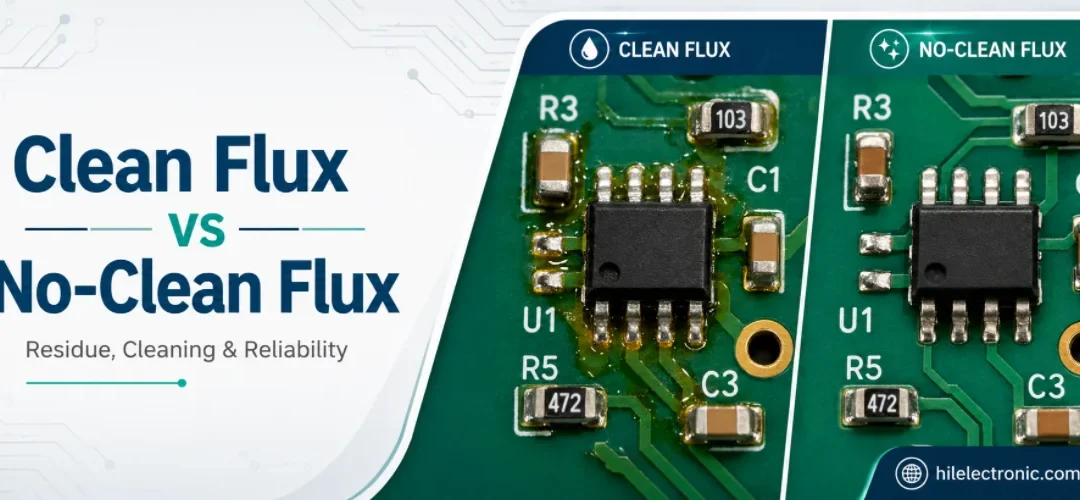
Clean Flux vs No-Clean Flux: Residue, Cleaning, and PCB Reliability
Figure 1. clean flux vs no-clean flux image for Highleap...
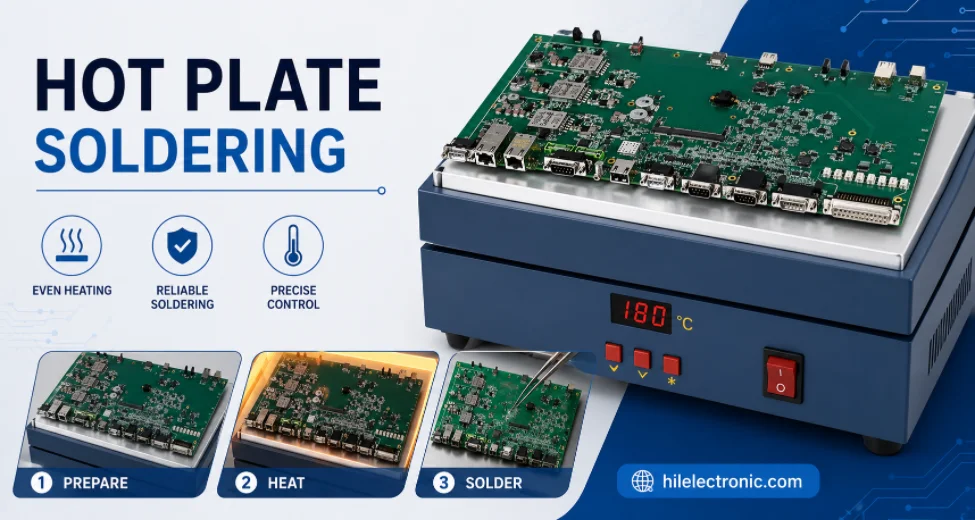
Hot Plate Soldering: Process, Limits, and Reflow Comparison
Figure 1. hot plate soldering image for Highleap...
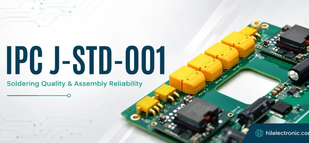
IPC J-STD-001: Classes, Requirements, and RFQ Specification
Figure 1. IPC J-STD-001 image for Highleap Electronics PCB...
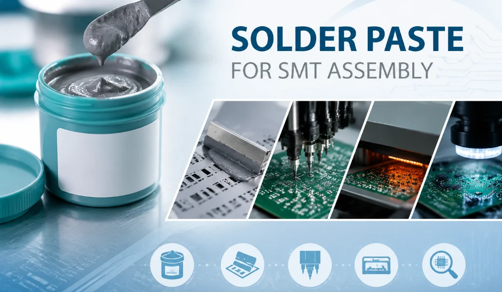
Solder Paste for SMT Assembly: Types, Storage, and Printing Defects
Figure 1. Solder paste selection affects SMT print...