
Back to blog
Common Issues That Delay Flex PCB Orders

Ordering flex PCBs (Printed Circuit Boards) online often presents a unique set of challenges that can lead to delays, particularly when dealing with rigid-flex or fully flex designs. Understanding and addressing these common issues can ensure a smoother manufacturing process and timely delivery. In this guide, we delve into the common pitfalls that can impede the progress of your flex PCB orders and provide practical solutions to avoid these delays.
1. Ensuring Complete and Accurate Data Sets
1.1 Full Set of Gerber Files
Gerber files are crucial for the accurate production of PCBs. These files provide a detailed graphical representation of the PCB, including the copper layers, solder mask, legend, and more. An incomplete set of Gerber files can result in the manufacturer lacking essential information, which in turn delays the process as they seek additional clarification. To avoid this, ensure that you submit a comprehensive set of Gerber files that include all layers and details required for accurate manufacturing. It’s essential to verify that each layer’s Gerber file corresponds to the correct PCB layer and that there are no missing or duplicated files.
1.2 Mechanical Drawing or Spec Sheet
The mechanical drawing or spec sheet details the PCB’s dimensions, tolerances, and special requirements. This document is vital for ensuring that the final PCB will fit the intended application and meet the required specifications. Without a complete mechanical drawing, there is a risk of misalignment and non-compliance with specifications, which can lead to costly rework and delays. Always include a detailed spec sheet with your order to avoid these issues. Ensure that the drawing includes all necessary details such as hole placements, component outlines, and any special treatments or finishes required.
1.3 Material Stack-Up
The material stack-up outlines the layers of materials used in the PCB, including core materials, copper layers, prepreg, and any special materials. It is critical for defining the electrical and mechanical properties of the PCB. An incomplete or incorrect material stack-up can lead to issues with performance and reliability. Ensure that your material stack-up includes detailed information about copper weight and desired thickness to meet your design requirements. For flex PCBs, the stack-up should also consider the flexibility and mechanical stress requirements of the design, including the thickness of the flexible substrates and any adhesive layers.
2. Addressing Design-Related Issues
2.1 Unsupported Component Areas
In flex PCB designs, placing components on unsupported areas can lead to mechanical stress during bending, potentially causing solder joint failure. To mitigate this risk, use stiffeners made from materials like FR4 or polyimide to provide additional support where components are mounted. This will help to prevent bending near components and protect solder joints from stress-related failures. Additionally, consider using reinforcement techniques such as local thickening or adding support pads in high-stress areas to enhance durability.
2.2 Bend Requirements in Component Areas
Designs that require bending near component areas can significantly increase the risk of solder joint failure. It’s essential to avoid placing components in areas that will be subject to bending. If bending is necessary, ensure it occurs away from critical components to reduce stress on solder joints and maintain the integrity of the PCB. Implement design features such as flexible trace routing and bend relief areas to accommodate necessary bends without compromising component stability.
2.3 Vias or Plated Through-Holes (PTH) in Flex Areas
Including vias or PTHs in areas that will be bent can create stress concentrators, leading to potential cracking and electrical failures. To avoid these issues, design the PCB layout to minimize or eliminate vias and PTHs in flexible sections. If vias are required, consider using advanced techniques such as laser-drilled microvias with relieved pad designs to reduce stress and prevent damage. Alternatively, explore the use of buried vias or blind vias that do not interfere with bend areas.
2.4 90-Degree Trace Corners in Flex Areas
Sharp 90-degree corners in trace routing within flex areas can lead to mechanical stress and trace breakage. Instead of sharp corners, use radiused corners to change the direction of traces. Radiused corners distribute bending stress more evenly and reduce the risk of breakage. A recommended guideline is to use a radius that is at least twice the width of the trace. This approach minimizes stress concentration and enhances the durability of the PCB.

3. Additional Design Considerations
3.1 Stiffeners
In many flex PCB designs, stiffeners are required to provide additional support. Specify the material (polyimide or FR4), thickness, and location of the stiffeners in your design to ensure proper functionality and durability. Stiffeners help maintain the integrity of the PCB during handling and operation, particularly in areas where mechanical stress is anticipated.
3.2 Pressure Sensitive Adhesives (PSAs)
PSAs are used to attach components or layers within the PCB enclosure. Include details about the type of adhesive used and its placement in your design documentation to ensure proper adhesion and performance. PSAs should be chosen based on their compatibility with the PCB materials and their ability to withstand operational stresses.
3.3 Assembly Reflow Requirements
If reflow assembly is needed, provide part numbers and assembly requirements in your documentation. This information helps ensure that the assembly process is carried out correctly and that the final product meets your specifications. Detailed instructions regarding reflow temperatures, times, and profiles can prevent issues during the assembly process.
3.4 EMI/RF Shield Layers
For designs requiring electromagnetic interference (EMI) or radio frequency (RF) shielding, specify whether the shield layers are single-sided or double-sided, and provide details on ground interconnect locations. This information is essential for effective shielding and to prevent electromagnetic interference, ensuring the PCB operates within its intended electromagnetic environment.
Conclusion
Avoiding common issues that lead to delays in flex PCB orders requires meticulous attention to detail in data submission and design. By ensuring that your data sets are complete and accurate, and by addressing design-related challenges proactively, you can minimize the risk of delays and ensure that your flex PCB is manufactured and delivered on time. Engage with your PCB manufacturer early in the design process to address any potential issues and to verify that your design meets all necessary specifications. A well-prepared design and thorough documentation can significantly enhance the efficiency of the manufacturing process, leading to timely delivery and high-quality results.

Recommended Posts

FPC PCB Design Guide for Flexible Printed Circuits
Flexible Printed Circuits (FPCs), also known as flexible...

Flex PCBA Services: Lightweight, Durable, and Ready for Any Application
Unlike traditional rigid PCBs, flexible PCBs use bendable...
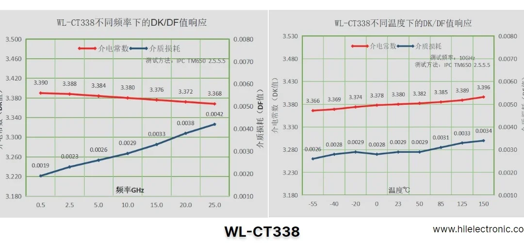
Custom WL-CT338 PCBs: Unlocking Performance for High-Tech Industries
At Highleap Electronic, we specialize in providing custom...

Custom Flex Board Production: Ultra-Long, Extra-Large, and Multi-Layer Designs
Flex boards, also known as flexible circuit boards (FPCs),...