
Exploring Digital Logic Design in PCB Circuitry

Introduction to Digital Logic Design and Its Role in PCB Manufacturing
Digital logic design is a crucial component of modern electronics and is essential for developing digital systems. It involves the creation of circuits that process binary signals (0s and 1s) and is foundational in devices ranging from simple calculators to complex microprocessors. For engineers and students in the field of electrical and computer engineering, mastering digital logic design is key to understanding how electronic systems work and how they can be improved. One critical aspect of this process is how digital logic design connects with PCB (Printed Circuit Board) manufacturing.
PCB manufacturing serves as the physical platform that supports and connects digital logic circuits, allowing them to function in real-world applications. Understanding the interaction between digital logic design and PCB manufacturing is vital for anyone involved in the development of electronic devices. From ensuring proper signal routing to managing power delivery and thermal dissipation, PCB design plays a crucial role in realizing the theoretical concepts behind digital logic designs. This integration is where digital logic design and PCB design converge to produce functional, reliable, and efficient electronic systems.
How Digital Logic Design Shapes PCB Development
Digital logic design is not only about creating functional circuits but also about ensuring that these circuits work reliably within a specific physical environment. In PCB development, every digital circuit must be carefully translated into physical components and connections. The design of digital systems must consider how signals travel across the board, how components are placed to minimize interference, and how power is distributed to prevent overheating and system failures.
When designing a PCB, engineers must integrate logic gates, registers, and flip-flops into a layout that supports the desired functionality of the digital system. The digital logic design dictates the need for specific components and connections, which are then implemented on the PCB. For example, a simple design like a digital clock requires counters, decoders, and flip-flops to function, all of which must be appropriately placed and routed on the PCB. Similarly, more complex designs, like microprocessors or signal processing units, require careful routing of high-frequency signals and implementation of power management solutions, all influenced by the digital logic design principles.
Key Concepts in Digital Logic Design for Beginners
Before diving into specific projects, it’s crucial to understand the core concepts that form the basis of digital logic design. At the heart of digital logic circuits are logic gates, which perform basic operations on one or more binary inputs to produce a single output. The main types of logic gates include AND, OR, NOT, NAND, NOR, XOR, and XNOR gates. Each gate has its unique function, and these gates are combined to create complex digital circuits that perform specific tasks.
Another foundational concept is Boolean algebra, a mathematical framework that allows engineers to simplify and manipulate digital circuits. Boolean algebra is essential for designing efficient circuits and optimizing their performance. Using Boolean operators such as AND, OR, and NOT, engineers can reduce the complexity of circuits, making them easier to design and implement.
Moreover, digital circuits can be categorized into combinational circuits (which generate outputs based solely on current inputs) and sequential circuits (which depend on both current inputs and previous states). Flip-flops and registers are key components in sequential circuits, allowing the system to store and manipulate data, making them crucial in more advanced digital logic systems such as microprocessors.
For sequential circuits, an essential step in the design process is constructing the original state diagram and state table. These tools help visualize how a circuit transitions between different states based on input conditions, ensuring correct functionality before implementation. By mapping out all possible states and transitions, engineers can identify potential design optimizations and troubleshoot issues efficiently.

Digital Logic Design Tools and Software: Essential for Beginners and Professionals
Digital logic design projects require specialized tools to build, test, and verify circuits. Here are some of the most popular tools and software used by both beginners and professionals in the field:
- Logic Gate Simulators
Logic gate simulators like Logisim or Digital Works allow you to visually design and simulate digital circuits. These simulators provide a user-friendly interface to place and connect logic gates, and they offer real-time simulation, helping users understand how their circuits behave before physical implementation. These tools are great for beginners who want to practice and experiment with basic digital designs. - Verilog and VHDL (Hardware Description Languages)
Verilog and VHDL are hardware description languages used to model digital systems at a high level. They allow designers to describe the behavior of circuits and simulate their functions before moving to physical hardware. These languages are commonly used in industry for designing complex systems like FPGAs and ASICs, making them a valuable skill for aspiring engineers. - FPGA Development Boards
FPGA (Field-Programmable Gate Array) development boards such as Xilinx or Altera boards offer the flexibility to design and test custom digital circuits. FPGAs allow users to implement digital circuits that can be reprogrammed for different tasks, providing an excellent platform for learning and experimentation. - Circuit Design Software
Circuit design software such as Altium Designer, KiCad, or Eagle PCB provides the tools necessary for creating circuit schematics and layouts for PCBs. These software packages also include simulation capabilities, allowing you to test your designs in a virtual environment before manufacturing them.
Using these tools, beginners can start simple and progress to more complex designs as their skills develop. Whether designing basic logic gates or complex systems like microprocessors, these tools provide the necessary framework to turn ideas into functional digital systems.
Beginner-Friendly Digital Logic Design Projects: Start Building Today
Digital logic design is an exciting and hands-on field, especially for beginners in electrical and computer engineering. By working on practical projects, you can apply theoretical knowledge, enhance problem-solving skills, and deepen your understanding of digital circuits. These beginner projects will provide you with a solid foundation, preparing you for more advanced work in digital system design. Here are a few excellent projects for beginners, each of which teaches critical concepts and helps you develop a strong grasp of digital logic design.
1. Digital Clock Circuit
A digital clock is one of the most popular and foundational projects for beginners in digital logic design. It involves designing a system that can keep track of time and display it on a set of seven-segment displays or an LED screen. This project introduces several essential components of digital systems, including counters, flip-flops, and timekeeping circuits.
The circuit needs to convert clock pulses into time units (seconds, minutes, hours) and display them. You will need to design and implement binary counters to track seconds, minutes, and hours, and use decoders to display the correct digits on the seven-segment displays. Along the way, you will learn how sequential circuits work, which are used for counting and tracking time, as well as how to handle the synchronization of events in digital systems. This project gives you an excellent introduction to clock management, which is a crucial concept in almost all digital systems.
2. Traffic Light Controller
A traffic light controller is another excellent beginner project that involves designing a system that controls the timing of the traffic lights at an intersection. This project introduces students to sequential logic circuits, state machines, and timing circuits, which are core components of most digital systems.
The goal is to design a circuit that can control the flow of traffic in an intersection by changing the lights at appropriate intervals (red, yellow, and green). This system must manage the timing for each light and ensure the right sequence for safe traffic flow. The challenge here is to implement a system that uses timing registers to keep track of each light’s state and switches the signals based on a predefined pattern. You’ll also explore the concept of timing control, understanding how to set delays and adjust timing intervals in digital systems. This project will help you grasp the practical application of state transitions and timing control in digital design.
3. Simple Calculator
A simple calculator is a more complex yet rewarding digital logic design project. It involves creating a system that can perform basic arithmetic operations such as addition, subtraction, multiplication, and division. This project teaches you how to handle multiple inputs, outputs, and data flow, providing a deeper understanding of combinational logic circuits.
In this design, you’ll need to create a circuit that accepts inputs (usually from a keypad) and displays the result on an output device, such as an LCD screen. The challenge here lies in designing arithmetic circuits that can process inputs and execute the correct operation. You’ll also explore how to use registers to temporarily store intermediate results. By working through this project, you’ll gain experience in designing multiplexer circuits for selecting operations, adders for performing calculations, and bistable circuits for memory storage. The simple calculator project not only teaches basic arithmetic logic but also introduces more advanced data manipulation and control flow techniques in digital systems.
4. Simple Alarm System
A simple alarm system is another engaging project for beginners. It involves designing a system that can detect specific conditions, such as motion or door sensors, and trigger an alarm when these conditions are met. This project is an excellent way to learn about sensor integration, event-driven logic, and alarm triggering circuits.
In this design, you will need to interface sensors, such as motion detectors or magnetic door switches, with digital logic circuits that can trigger an alert when an abnormal condition occurs (e.g., detecting movement or an open door). You’ll learn how to process input from sensors and translate that into a digital signal using combinational circuits or comparators. Once the input is processed, the system should activate an alarm, either a buzzer or visual indicator (like an LED). The project teaches you how to integrate sensors and signals into digital circuits, along with understanding event-driven logic, which is crucial in applications like security systems and automation.
Building Confidence and Moving to Advanced Projects
These beginner projects provide a robust foundation for anyone starting their journey in digital logic design. Each of these projects covers essential concepts such as counters, sequential logic, arithmetic circuits, sensor integration, and more. They help you practice problem-solving and gain hands-on experience with digital components and systems.
As you progress through these projects, you’ll not only enhance your understanding of digital logic but also gain confidence in designing more complex systems. The skills learned here will lay the groundwork for more advanced digital designs, such as microprocessor development, communication systems, and robotics.
The best part is that these projects are scalable, allowing you to start with the basics and then add more features as your skills grow. Whether you’re a student or an enthusiast, diving into these hands-on projects will help you master the fundamentals of digital logic and open doors to exciting opportunities in engineering and technology.
If this requirement affects sourcing or production release, compare it with electronic component sourcing and flexible circuit fabrication before sending the final files for review.

Exploring Advanced Digital Logic Design Concepts: From FPGAs to Microprocessor Design
As digital technology continues to advance, mastering complex digital logic design concepts becomes essential for engineers and students looking to stay ahead in the field. Field-Programmable Gate Arrays (FPGAs) are one such concept, offering unmatched flexibility in implementing custom digital logic circuits. These reprogrammable devices are widely used in high-performance applications such as digital signal processing, telecommunications, and embedded systems. Their ability to be reprogrammed for different tasks makes them invaluable for rapid prototyping and experimentation. Engineers use FPGAs to test new ideas and optimize digital circuits without the need for expensive and time-consuming chip fabrication.
High-Speed Digital Design: Ensuring Signal Integrity at High Frequencies
High-Speed Digital Design is another crucial area for those interested in advanced digital logic systems. In high-speed applications, the challenge lies in maintaining signal integrity as circuit speeds increase. Factors like signal delay, crosstalk between traces, and power consumption become more critical as frequencies rise. For example, in telecommunications and high-frequency trading, a small error in signal timing can lead to catastrophic failures. Thus, designing circuits capable of operating reliably at high frequencies requires careful attention to layout, trace impedance, and the use of specialized materials to ensure that signal degradation is minimized. Proper planning and advanced techniques such as controlled impedance traces, differential signaling, and shielding can mitigate signal integrity issues and improve circuit reliability at high speeds.
Low-Power Digital Design: Optimizing Efficiency for Portable Devices
In the era of portable devices, Low-Power Digital Design has become essential. Power consumption is a major concern, especially in battery-operated devices like smartphones, wearables, and IoT devices. Designers must optimize circuits to minimize energy usage without sacrificing performance. Techniques such as clock gating, power gating, and voltage scaling are used to reduce power consumption in active and idle states. Additionally, the selection of energy-efficient components and careful design of power delivery networks is critical for achieving the balance between high performance and low energy use, which is essential in mobile and IoT technologies. Power-efficient microprocessors, memory management, and low-power signal processing techniques are key factors in developing reliable, long-lasting devices that can operate continuously on a single charge.
Microprocessor Design: The Heart of Computing Systems
Microprocessor Design is one of the most challenging and sophisticated aspects of digital logic. Creating a microprocessor requires a deep understanding of digital circuits, memory systems, and how instructions are executed by the processor. Advanced techniques such as pipelining, branch prediction, and superscalar architecture are used to enhance the processor’s performance. The design process also includes considerations for peripheral interfacing, memory management, and input/output systems. Microprocessor design is crucial not only for traditional computing but also for embedded systems, where custom processors are often needed to meet specific performance and power requirements. Understanding how to design a microprocessor equips engineers with the skills to create custom hardware for a variety of applications. This process includes designing the processor’s core, cache systems, and addressing modes to enable efficient computation across a wide range of tasks.
Get a Free PCB & PCBA Quote

Recommended Posts

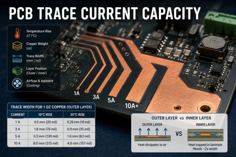
PCB Current Calculator: Sizing Trace Width and Vias with the IPC-2221 Formula
Figure 1. Pcb Current Calculator reference image for PCB...
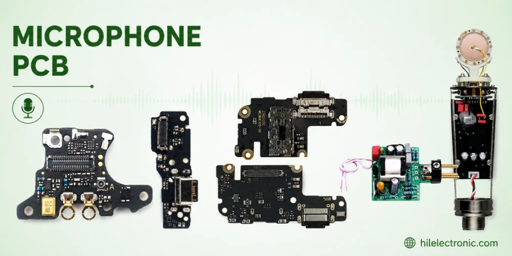
Microphone PCB Design: How the Board Itself Shapes Your Audio Quality
Figure 1. Microphone Pcb reference image for PCB...
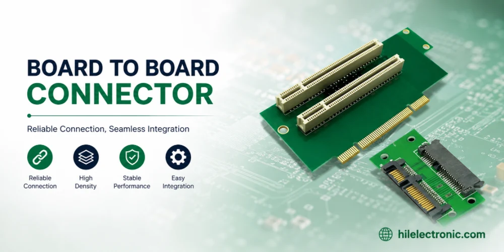
Board-to-Board Connector: Types, Specifications, and How to Select One
Figure 1. Board To Board Connector reference image for PCB...
PCB Trace Width Calculator: How to Size Traces for Current, Voltage Drop, and Impedance
Figure 1. A PCB trace width calculator is a starting point...
How to get a quote for PCBs
Let us run DFM/DFA analysis for you and get back to you with a report.
You can upload your files securely through our website.
We require the following information in order to give you a quote:
-
- Gerber, ODB++, or .pcb, spec.
- BOM list if you require assembly
- Quantity
- Turn time
In addition to PCB manufacturing, we offer a comprehensive range of electronic services, including PCB design, PCBA (Printed Circuit Board Assembly), and turnkey solutions. Whether you need help with prototyping, design verification, component sourcing, or mass production, we provide end-to-end support to ensure your project’s success. For PCBA services, please provide your BOM (Bill of Materials) and any specific assembly instructions. We also offer DFM/DFA analysis to optimize your designs for manufacturability and assembly, ensuring a smooth production process.