
HDI PCB Technology: Enabling Advanced Semiconductor Packaging Solutions

Introduction: The Evolution Toward Higher Density Interconnects
Modern semiconductor packaging demands increasingly sophisticated interconnect solutions. As chip geometries shrink and I/O counts rise, traditional printed circuit boards cannot adequately support advanced packaging architectures like system-in-package (SiP), chip-scale packages (CSP), and fan-out wafer-level packaging (FOWLP).
HDI PCB technology addresses this gap by delivering finer line widths, smaller via structures, and higher routing density comparable to package substrates. This article examines how HDI and Substrate-Like PCB (SLP) technologies bridge conventional PCB manufacturing and IC substrate fabrication, particularly for packaging carriers, redistribution layers, and chip-level interconnections.
Defining HDI PCB, SLP, and IC Substrate Technologies
High-Density Interconnect PCB Fundamentals
HDI PCB employs microvias formed through laser drilling, sequential build-up layers, blind and buried vias, and via-in-pad configurations. These boards typically feature line widths and spacings ranging from 75/75 μm down to 40/40 μm, with microvia diameters between 100-150 μm. The build-up process adds thin dielectric and copper layers sequentially, enabling complex routing in compact form factors essential for mobile devices and high-performance computing applications.
Substrate-Like PCB: Bridging Two Worlds
Substrate-Like PCB occupies the design space between advanced HDI and true IC package substrates. SLP maintains panel-level PCB manufacturing processes while achieving line/space geometries approaching 20/35 μm through semi-additive processes (SAP). This approach delivers substrate-grade density at lower costs than traditional IC substrates, making it attractive for applications requiring high interconnect density without full substrate-level investment.
Comparative Positioning of HDI PCB Technologies
The positioning between these technologies reflects distinct manufacturing capabilities and cost structures:
- HDI PCB – Suitable for 50-100 μm features using conventional PCB materials and processes
- Substrate-Like PCB – Achieves 20-35 μm geometries through modified SAP processing on panel equipment
- IC Package Substrates – Delivers sub-20 μm features with specialized BT/ABF materials but requires significant capital investment
SLP provides an intermediate solution, leveraging modified PCB equipment to approach substrate performance while maintaining PCB economics through panel processing.

HDI PCB & Substrate-Like PCB & IC Substrate
HDI PCB Structure and Process Technologies
Build-Up Architecture Variants
Modern HDI PCB structures employ multiple configurations depending on density requirements. Stacked microvias create vertical interconnects through multiple build-up layers, minimizing routing distance for high-speed signals. Staggered microvia designs distribute mechanical stress and improve reliability under thermal cycling, while buried vias within the core layer enable complex routing topologies.
Laser Microvia Formation in HDI PCB
Laser drilling using CO₂ or UV lasers creates controlled-depth microvias with diameters as small as 75-100 μm. The process ablates dielectric material to expose underlying copper pads, which are then desmeared and metalized through electroless copper deposition followed by pattern plating. Laser parameters including pulse energy, frequency, and focus must be precisely controlled to prevent substrate damage while ensuring clean via formation.
Semi-Additive and Fully-Additive Processes
Semi-additive processes enable ultra-fine line formation in SLP applications by depositing thin copper seed layers, applying photoresist, and plating conductor patterns before removing excess seed copper. This approach achieves 20-30 μm line widths compared to 75-100 μm typical for subtractive etching. Modified SAP (mSAP) processes further refine this capability, approaching substrate-level geometries while maintaining compatibility with standard PCB materials.
Material Systems for Advanced HDI Applications
High-performance HDI PCB applications require materials with controlled coefficient of thermal expansion (CTE), low dielectric constant, and high glass transition temperature (Tg). Modified FR-4 formulations with Tg above 170°C provide adequate performance for consumer electronics, while polyimide films offer superior thermal stability for rigid-flex constructions. BT and ABF materials enable SLP designs to achieve thermal and electrical properties approaching package substrates.
HDI PCB Design Considerations for Manufacturing Success
Geometric Specifications and Electrical Performance
Design rules for HDI PCB must account for achievable line width and spacing relative to copper weight and process capabilities. Designs targeting 40/40 μm geometries require half-ounce copper with tight etching controls, while SLP designs approaching 25/25 μm demand SAP processing.
Impedance control becomes increasingly critical as trace dimensions shrink, requiring precise dielectric thickness control and copper profile management. Differential pair routing must account for tighter coupling and increased susceptibility to adjacent layer crosstalk as routing density increases.
Thermal and Mechanical Reliability
Copper distribution significantly impacts board warpage in HDI structures due to CTE mismatch between materials. Design strategies to ensure reliability include:
- Symmetrical copper balancing – Distributes copper weight across board centerline to minimize warpage
- Staggered via patterns – Reduces stress concentrations and improves mechanical integrity
- Via-in-pad thermal paths – Provides direct heat flow from components to internal power planes
- Copper-filled microvias – Enables multiple reflow cycles without via degradation in BGA applications
Panel-Level Processing Constraints
Panel fabrication enables cost-effective HDI PCB manufacturing but introduces uniformity challenges absent in substrate manufacturing. Laser drilling accuracy varies across panel area, requiring statistical process controls and positioning calibration. Copper plating thickness distribution across large panels affects impedance consistency, requiring careful design layouts that position critical features to minimize edge effects.

Semiconductor Packaging
Meeting Semiconductor Packaging Requirements with HDI PCB
Advanced Package Integration
HDI PCB technology serves as an enabling platform for heterogeneous integration in advanced packaging architectures. In fan-out panel-level packaging, HDI boards provide the redistribution layer substrate with fine-pitch routing connecting die to package-level interconnects.
For 2.5D integration, high-density interposers built using SLP technology offer cost advantages over silicon interposers for applications tolerating moderate signal densities. Module substrates incorporating multiple die, passive components, and shielding structures rely on HDI capabilities to achieve required I/O densities within compact footprints.
Mobile and Wearable Applications
Smartphone mainboards exemplify HDI PCB density requirements, typically featuring 8-12 build-up layers with 50/50 μm line/space geometries supporting component pitches down to 0.35 mm. Any-layer HDI structures enable arbitrary via placement, maximizing routing efficiency in space-constrained designs. Rigid-flex HDI constructions integrate flexible interconnects within build-up structures, eliminating connectors and reducing assembly thickness for wearable devices and foldable smartphones.
Quality Assurance and Process Validation for HDI PCB
Critical Inspection Methodologies
Quality control for HDI PCB manufacturing employs multiple verification techniques at various process stages:
- Automated optical inspection (AOI) – Verifies conductor pattern integrity, via registration accuracy, and surface finish quality
- X-ray inspection – Reveals internal via formation quality, including barrel continuity and potential voiding
- Cross-sectional analysis – Validates layer registration, dielectric thickness, copper plating uniformity, and via formation quality
These techniques establish process capability baselines essential for reliable volume production of complex HDI structures.
Electrical and Reliability Testing
Four-point resistance measurements verify via chain continuity and conductor resistance within specification limits. Time-domain reflectometry (TDR) validates impedance profiles along critical signal paths, identifying discontinuities from via transitions or geometry variations.
Thermal cycling between -55°C and 125°C for 500-1000 cycles stresses interconnects, revealing latent defects in via barrel adhesion or pad-to-via interfaces. Highly accelerated stress testing (HAST) at elevated temperature and humidity exposes susceptibility to conductive anodic filament (CAF) formation in fine-pitch geometries.
Cost Structure and Supply Chain Factors
Economic Positioning of HDI PCB Solutions
Substrate-Like PCB achieves 30-50% cost reduction compared to traditional IC substrates by leveraging panel processing, standard PCB materials, and existing manufacturing infrastructure with targeted equipment upgrades. However, SLP costs exceed conventional HDI by 20-40% due to specialized laser drilling requirements, SAP processing, and tighter process controls. Volume production amortizes capital investment across panel quantities, making HDI and SLP economically attractive for applications requiring thousands to millions of units annually.
Manufacturing Capability Requirements
Producing advanced HDI PCB requires laser drilling systems with precise depth control and positioning accuracy, ultra-fine line etching or SAP capabilities, and automated optical inspection systems capable of detecting sub-50 μm defects. Supply chain considerations include availability of appropriate dielectric materials, thin copper foils below 12 μm thickness, and specialized surface finishes compatible with fine-pitch assembly. Lead times typically range from 2-4 weeks for HDI PCB compared to 6-10 weeks for package substrates.
Future Trajectory of HDI PCB Technology
The boundary between PCB and IC substrate technologies continues blurring as manufacturing capabilities converge. Semi-additive processes are extending toward panel-level production of sub-20 μm features, challenging traditional substrate domain. Glass core substrates emerging for high-performance computing applications leverage PCB-style panel processing while delivering substrate-grade electrical performance and dimensional stability.
Advanced HDI PCB incorporating embedded die, passive components, and active devices within build-up layers represents the next frontier, transforming printed circuit boards from passive interconnect platforms into active system integration vehicles. As semiconductor packaging evolves toward chiplet architectures and heterogeneous integration, HDI and SLP technologies will play increasingly central roles in enabling cost-effective, high-performance interconnect solutions.
Conclusion
HDI PCB technology has evolved from a specialty capability to a mainstream solution for advanced semiconductor packaging and high-density electronic systems. The convergence of PCB and substrate manufacturing processes through Substrate-Like PCB approaches provides designers with flexible options spanning the continuum from traditional HDI to near-substrate performance levels. As line widths continue shrinking and packaging architectures become more complex, HDI PCB will remain essential for cost-effective implementation of next-generation electronic products.
Highleap Electronics: Your Partner for Advanced HDI PCB Manufacturing
Highleap Electronics delivers comprehensive HDI PCB and assembly solutions tailored for semiconductor packaging applications:
- Advanced HDI capabilities – Laser microvia drilling, build-up layer processing, and any-layer HDI structures supporting geometries down to 30/30 μm
- Substrate-Like PCB expertise – Semi-additive process implementation for ultra-fine line formation approaching substrate-grade densities
- Integrated assembly services – Fine-pitch BGA placement, component embedding, and rigid-flex assembly under one roof
- Quality assurance – Full inspection protocols including AOI, X-ray, cross-sectional analysis, and reliability testing
- Design support – DFM analysis and stack-up optimization to ensure manufacturability and performance
Contact our engineering team to discuss how our HDI PCB manufacturing capabilities can accelerate your product development and optimize your supply chain for advanced packaging applications.

Recommended Posts
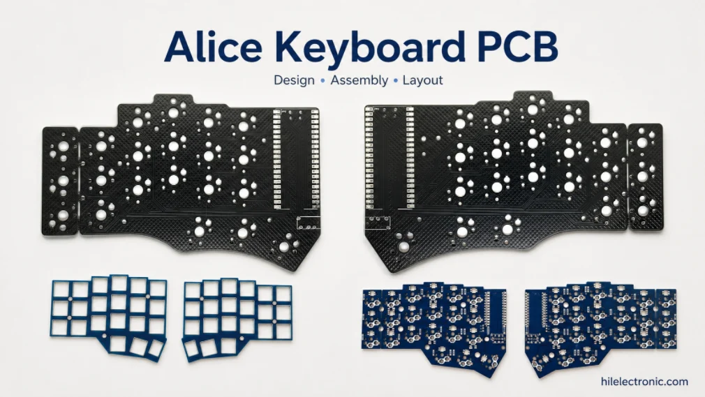
Alice Keyboard PCB Manufacturer | Custom Ergonomic Layout
An Alice keyboard PCB manufacturer must translate an...
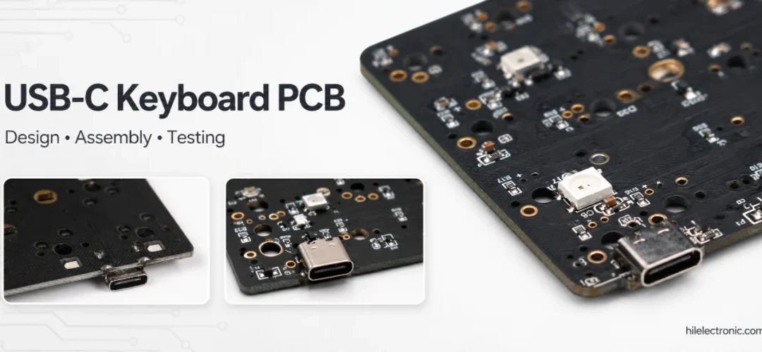
USB-C Keyboard PCB Manufacturer | ESD & Power Protection
A USB-C keyboard PCB manufacturer must control the...

Per-Key RGB Keyboard PCB Manufacturer & LED Assembly
A per-key RGB keyboard PCB manufacturer must control far...

Ortholinear Keyboard PCB Manufacturer | Custom Grid Layout
An ortholinear keyboard PCB manufacturer must preserve a...
How to get a quote for PCBs
Let‘s run DFM/DFA analysis for you and get back to you with a report. You can upload your files securely through our website. We require the following information in order to give you a quote:
-
- Gerber, ODB++, or .pcb, spec.
- BOM list if you require assembly
- Quantity
- Turn time
In addition to PCB manufacturing, we offer a comprehensive range of electronic services, including PCB design, PCBA, and turnkey solutions. Whether you need help with prototyping, design verification, component sourcing, or mass production, we provide end-to-end support to ensure your project’s success.
For PCBA services, please provide your BOM (Bill of Materials) and any specific assembly instructions. We also offer DFM/DFA analysis to optimize your designs for manufacturability and assembly, ensuring a smooth production process.