
End-to-End PLC Circuit Board Manufacturing for Custom Designs

When a PLC circuit board fails, production stops. Every hour of downtime in a manufacturing facility carries a direct cost measured in lost output, emergency labor, and schedule disruption. Whether the board that failed is a CPU module, a digital I/O card, a power supply board, or an analog input module, the question that matters most is how to get the correct replacement into the system as quickly as possible, with confidence that it will perform reliably for years to come.
At Highleap Electronics, we manufacture custom PLC PCBs for OEM platforms, replacement boards for legacy and discontinued systems, and new programmable logic controller boards from original designs. This guide addresses the full range of situations engineers and maintenance teams face when they need a PLC circuit board built correctly and delivered on schedule.
Table of Contents
- Understanding the PLC Circuit Board: What It Is and What It Does
- Common PLC Circuit Board Failure Modes and Root Causes
- Repair, Replace, or Custom Fabricate: How to Choose the Right Path
- How to Source a Replacement PLC Circuit Board
- Reverse Engineering Legacy and Obsolete PLC Circuit Boards
- Custom PLC Circuit Board Fabrication for OEM and End-User Applications
- Highleap’s PLC Circuit Board Manufacturing Capabilities
- Quality Standards That Define Industrial PLC Circuit Board Reliability
- What Files We Need for a PLC Circuit Board Quote
- PLC Circuit Board FAQ
Understanding the PLC Circuit Board: What It Is and What It Does
A PLC circuit board—also called a PLC PCB, PLC control board, or PLC main board—is the printed circuit board that implements the core functions of a programmable logic controller. It is not simply a carrier for components. It is a precision-engineered assembly where substrate selection, layer construction, trace routing, and component placement collectively determine how reliably the system performs across its full service life in an industrial environment.
Most PLC systems consist of several distinct board types, each serving a specific function:
- CPU board: houses the main processor, program memory, system memory, communication controllers, and real-time clock. This is typically the most complex and highest-value board in the system, and often the most difficult to replace when it becomes obsolete.
- Power supply board: converts AC or DC input power to the regulated voltages needed by CPU, I/O modules, and communication interfaces. Power supply board quality directly protects the entire system from transient damage.
- Digital input board: receives signals from field devices such as switches, proximity sensors, encoders, and push buttons, then converts them to logic levels the CPU can process. Optical isolation on each input channel protects the CPU from field fault voltages.
- Digital output board: drives actuators such as solenoids, motor starters, indicator lights, and valve coils from CPU command signals. Output protection against inductive kickback and short-circuit conditions is critical for board longevity.
- Analog I/O board: handles 4–20mA current loop signals, 0–10V voltage inputs, and thermocouple or RTD temperature inputs. Channel accuracy, common-mode rejection, and isolation determine measurement quality and calibration stability.
- Communication board: provides network connectivity through protocols such as EtherCAT, PROFINET, Ethernet/IP, Modbus TCP, DeviceNet, or PROFIBUS. These boards often require controlled impedance fabrication for reliable high-speed communication.
When any of these boards fails—or when a system expansion requires an additional module—the ability to source a correctly specified replacement quickly is what determines how long the production line stays down.
Get a Custom PLC Circuit Board Quote
Common PLC Circuit Board Failure Modes and Root Causes
Understanding why PLC circuit boards fail is the first step toward getting the right solution—and toward specifying replacement boards that will not fail the same way in the same environment.
| Failure Mode | Typical Cause | Boards Most Affected |
|---|---|---|
| Electrolytic capacitor degradation | Temperature cycling, age, high ripple current | Power supply boards, CPU boards |
| Transient voltage damage | Inductive switching events, lightning, ground faults exceeding TVS rating | Digital input boards, analog input boards |
| Optical isolator degradation | Overcurrent through LED section, UV exposure, end of rated life | Digital input and output boards |
| Solder joint fatigue | Thermal cycling stress at through-hole component leads with high mass | Power supply boards, high-current output boards |
| Trace corrosion and delamination | Humidity ingress, chemical exposure, aged surface finish on standard FR4 | All board types in unprotected or high-humidity enclosures |
| BGA solder joint failure | Thermal cycling stress under large BGA packages on boards with inadequate material selection | CPU boards with advanced processors |
| Firmware and memory corruption | Backup battery failure, power interruption during write cycle, excessive write cycles on flash | CPU boards |
Capacitor failure and transient damage together account for a large share of PLC circuit board failures in industrial service. When a power supply board fails due to capacitor degradation, the first symptoms frequently appear as intermittent CPU faults, communication dropouts, or unexpected output state changes—symptoms that are easily misdiagnosed as software or network problems before the hardware root cause is identified.
Repair, Replace, or Custom Fabricate: How to Choose the Right Path
When a PLC circuit board fails, three resolution paths are available: repair the existing board at the component level, replace it with an equivalent unit, or have a custom replacement fabricated. The correct choice depends on the board’s age, OEM availability, application criticality, and long-term supply requirements.
| Situation | Recommended Path | Key Consideration |
|---|---|---|
| Current production board with isolated component failure | Component-level repair | Only viable if root cause is confirmed and the repair facility has the correct parts in stock |
| Current board, failure cause unclear or damage is extensive | Replace with identical OEM unit | Fastest resolution if OEM stock is available; verify hardware revision and firmware compatibility |
| Legacy board; OEM discontinued or lead times are unacceptable | Reverse-engineered custom replacement fabrication | Eliminates ongoing OEM dependency and can provide long-term supply security |
| New proprietary PLC platform development | Custom PLC PCB design and fabrication | Full control over design, cost structure, and supply chain from the start |
| OEM board available but expensive; multiple units needed | Custom fabrication of equivalent board | Volume pricing often provides a significant cost advantage over OEM replacement pricing |
For maintenance teams managing aging industrial equipment, the most common hidden cost is discovering that a replacement PLC board is no longer available from the original manufacturer when the next failure occurs. Establishing a relationship with a manufacturer who can produce custom replacements on demand—or building a verified stock of reverse-engineered boards—eliminates that risk before it becomes a production crisis.
How to Source a Replacement PLC Circuit Board
Sourcing a replacement PLC circuit board correctly requires matching several specifications beyond the part number alone. Hardware revision, firmware compatibility, I/O channel configuration, and communication protocol version all affect whether a replacement board will function correctly within the existing system.
Steps to complete before ordering a replacement:
- Identify the exact hardware revision: PLC boards are often revised during production lifecycles. Hardware revision is typically printed on the board silkscreen or a label attached to the housing. Installing a different revision can cause firmware incompatibilities or require a full system configuration update before the replacement will operate correctly.
- Check firmware version requirements: Some hardware revisions require minimum firmware versions in the CPU module. Verify current system firmware before ordering a replacement to avoid compatibility problems that extend downtime after the board physically arrives.
- Confirm I/O channel count and signal specifications: Replacement boards must match the original I/O count, signal voltage range, input filter time constants, and output type—transistor, relay, or triac.
- Verify communication interface details: If the board includes a network interface, the communication protocol, data rate, and connector type must match the existing system network configuration.
- Assess long-term availability before ordering a single replacement: If the original board is approaching end-of-life or OEM support is uncertain, planning for custom fabrication now is less disruptive than managing an emergency replacement crisis later.
When OEM stock is unavailable or lead times are unacceptable for a production-critical system, custom fabrication of a functionally equivalent replacement is often the fastest practical solution—particularly when the alternative is waiting weeks or months for an OEM unit that may no longer be manufactured.
Reverse Engineering Legacy and Obsolete PLC Circuit Boards
Legacy PLC systems routinely remain in industrial service for 20 to 30 years. When the original manufacturer discontinues a board, ends support, or ceases operations entirely, the only reliable long-term solution is a custom-fabricated replacement built from reverse-engineered production data. Highleap can support the complete reverse engineering process from physical board through verified production Gerber files.
The reverse engineering process for a PLC circuit board typically covers:
- Physical inspection and documentation: layer count, board dimensions, component types and placement positions, connector locations, and overall construction are documented from one or more original board samples.
- X-ray and layer characterization: For multilayer boards, internal routing and via structure must be characterized. X-ray imaging reveals via locations and internal copper patterns without destructive analysis.
- Schematic reconstruction: Net connectivity is traced from the physical board to reconstruct the electrical schematic, which is verified against known functional behavior of the original system before production files are generated.
- Component identification and sourcing review: Components are identified by visible part markings where available. For proprietary or obsolete ICs, equivalent replacement components are identified and validated during the prototype stage.
- Gerber file generation and DFM review: Production-ready files are generated and reviewed for fabrication feasibility before the first prototype build is released.
- Functional prototype verification: Prototype boards are tested against the original system’s functional specifications and field behavior before production quantities are approved.
Customers who invest in reverse engineering establish a permanent, independently owned design that can be manufactured on demand—fully independent of OEM parts availability, OEM pricing, or OEM corporate decisions about product support timelines.
Custom PLC Circuit Board Fabrication for OEM and End-User Applications
For OEMs developing new PLC platforms, and for end users who want to replace proprietary third-party systems with fully owned designs, custom PLC circuit board fabrication provides complete control over performance, cost, and supply chain. The design requirements for a reliable industrial PLC board are well-defined, and working with a manufacturer who provides engineering feedback during the design phase significantly reduces development risk and time to production.
Key design decisions that shape custom PLC circuit board fabrication outcomes:
- Processor and memory architecture: The choice of CPU architecture, memory technology, and supporting chipset determines processing capability and influences layer count requirements for the board stack-up.
- I/O architecture—integrated versus modular: Whether I/O is implemented on the main CPU board or on separate modular expansion boards affects the mechanical form factor and board-to-board interconnect design.
- Communication protocol support: Industrial Ethernet protocols often require controlled impedance fabrication and specific differential pair routing strategies; legacy serial protocols are less demanding but still require careful layout for EMC compliance.
- Power architecture and input range: Input voltage range, regulation topology, and power sequencing affect both the power supply section design and the decoupling strategy across the complete board assembly.
- Certification requirements: CE marking, UL listing, and application-specific certifications such as SIL ratings for safety PLCs drive isolation requirements, clearance and creepage specifications, and quality expectations from the outset of the design.
For new platform designs, early engagement with our engineering team through prototype PCB manufacturing helps verify the design approach before volume production is committed.
Highleap’s PLC Circuit Board Manufacturing Capabilities
Highleap Electronics provides custom PCB fabrication for PLC circuit boards across the full range of complexity—from 4-layer digital I/O boards to 12-layer CPU boards with controlled impedance communication layers, high-reliability inspection, and mixed SMT and through-hole assembly.
| Capability | Detail |
|---|---|
| Layer count | 2 to 20+ layers for all PLC board types |
| Base materials | Standard FR4, high-Tg FR4, halogen-free laminates, polyimide, metal-core options |
| Copper weight | 0.5 oz to 8 oz; heavier copper for high-current power rails and output stages |
| Surface finish | ENIG, HASL, ENEPIG, OSP, immersion silver—selected by application and connector requirements |
| Controlled impedance | ±10% and ±5% tolerance supported for communication and high-speed signal layers |
| IPC compliance | Class II and high-reliability fabrication and inspection support, depending on project requirements |
| Testing | 100% electrical test, AOI, impedance verification, cross-section analysis for qualification builds |
| Production stage | Prototype through mass production; engineering review at all stages |
| Special capabilities | Isolation routing slots, press-fit connector zones, selective surface treatment, edge plating, via-in-pad with fill |
For customers who need both bare board fabrication and fully assembled PLC circuit boards, we coordinate the complete manufacturing flow to maintain quality consistency from fabrication through assembly, test, and delivery.
Quality Standards That Define Industrial PLC Circuit Board Reliability
Industrial PLC circuit boards are held to higher standards than commercial electronics because failures are measured in production downtime, safety incidents, and equipment damage rather than customer inconvenience. Specifying the correct quality level from your manufacturer is as important as specifying the correct material.
- IPC-A-600 (Acceptability of Printed Boards): defines visual acceptability criteria for bare circuit boards. Higher-reliability industrial PLC applications often require stricter acceptability criteria than commercial electronics.
- IPC-A-610 (Acceptability of Electronic Assemblies): defines acceptability criteria for populated assemblies and is widely used for quality inspection of industrial electronics.
- IPC-2221 (Generic Standard on Printed Board Design): provides design guidelines including minimum clearance and creepage distances for different voltage levels—directly applicable to PLC boards carrying mixed voltage domains.
- IEC 61010-1 (Safety Requirements for Electrical Equipment for Measurement, Control, and Laboratory Use): a key product safety standard for industrial control equipment, defining isolation, clearance, and creepage requirements for mains-connected PLC designs.
- IEC 61131-2 (PLC Hardware Requirements): specifies environmental and electrical performance requirements for PLC hardware, including EMC immunity levels for conducted and radiated interference.
When requesting PLC circuit board fabrication, always specify the reliability and inspection level at the time of order. A manufacturer who applies the same default inspection standard to every board may not be meeting the criteria your application requires—and you may not discover this until a field failure occurs.
What Files We Need for a PLC Circuit Board Quote
Getting an accurate quote for a PLC circuit board—whether for a new design, a direct replacement, or a reverse-engineered legacy part—requires providing enough information for the manufacturing team to understand both the electrical requirements and the environment the board will operate in.
For a new or custom design, the complete quote package includes:
- Gerber files or ODB++ data covering all copper layers, solder mask, silkscreen, drill files, and board outline
- Stack-up specification with material selection, layer count, copper weight per layer, target finished thickness, and any controlled impedance requirements
- Fabrication notes specifying reliability level, surface finish, isolation slot locations, press-fit zones, and any other special requirements
- Quantity and lead time requirements for both prototype and planned production volumes
For replacement or reverse-engineered PLC circuit boards, provide as much information as is available about the original board: the original part number and hardware revision, layer count if known, and any context about the application environment and reliability requirements.
Our engineering team reviews every PLC circuit board quote submission to identify DFM issues, material concerns, or manufacturing risks before committing to a build—helping avoid common causes of rework and schedule delay in industrial control board production.
If you are preparing a new project, submit your files through our PCB quote page or explore our full PCB fabrication services for production planning support.
Get a Quote for Your PLC Circuit Board
PLC Circuit Board FAQ
Can you fabricate a replacement for a PLC circuit board that is no longer available from the original manufacturer?
Yes. We can work from Gerber files you already have, or support the reverse engineering of an existing board to create production-ready fabrication data. Replacing discontinued OEM boards with custom-fabricated equivalents is one of the most common requests we receive from maintenance and engineering teams managing legacy industrial systems.
What information is needed to reverse engineer a PLC circuit board?
A physical sample of the original board is the starting point. Any supporting documentation—schematics, assembly drawings, OEM datasheets—helps reduce the time and cost of the process. Layer count, known component information, and application context about operating environment and reliability requirements also contribute to a faster and more accurate result.
How do I verify that a replacement PLC circuit board will work in my existing system?
Hardware revision, firmware version compatibility, I/O channel configuration, and communication interface type all need to match the original board. Document these specifications from the installed system before ordering any replacement. Our team can help review compatibility requirements when the situation is complex or when original documentation is incomplete.
What surface finish is most appropriate for PLC circuit boards?
ENIG is a common recommendation for many PLC circuit boards. It provides a flat, oxidation-resistant, and solderable surface suitable for fine-pitch SMT components, edge connectors, and press-fit terminal headers. For boards with predominantly through-hole assembly and no fine-pitch SMD components, HASL can be a cost-effective alternative.
Can PLC circuit boards be manufactured to higher reliability requirements?
Yes. We support higher-reliability fabrication and inspection requirements for PLC circuit boards used in demanding industrial applications. These requirements should be specified at the time of order so the appropriate inspection and process controls are applied throughout manufacturing.
What is the typical lead time for prototype PLC circuit boards?
For standard multilayer prototype builds, lead times typically range from 5 to 15 working days depending on layer count, material selection, and any special requirements such as controlled impedance or enhanced inspection. Rush fabrication is available for urgent maintenance and production recovery situations.
Do you support PCB assembly for PLC circuit boards as well as bare board fabrication?
Yes. Highleap provides PCB assembly alongside bare board fabrication, supporting SMT, through-hole, and mixed assembly processes for PLC circuit boards. Coordinating both fabrication and assembly with a single supplier simplifies the production process and helps maintain quality control across the complete manufacturing flow.

Recommended Posts

Per-Key RGB Keyboard PCB Manufacturer & LED Assembly
A per-key RGB keyboard PCB manufacturer must control far...

Ortholinear Keyboard PCB Manufacturer | Custom Grid Layout
An ortholinear keyboard PCB manufacturer must preserve a...
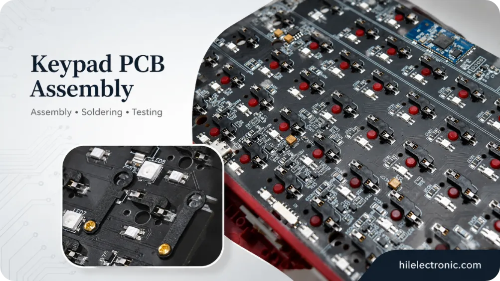
Keypad PCB Assembly Manufacturer | Custom Control Keypads
A keypad PCB assembly manufacturer may be building a...
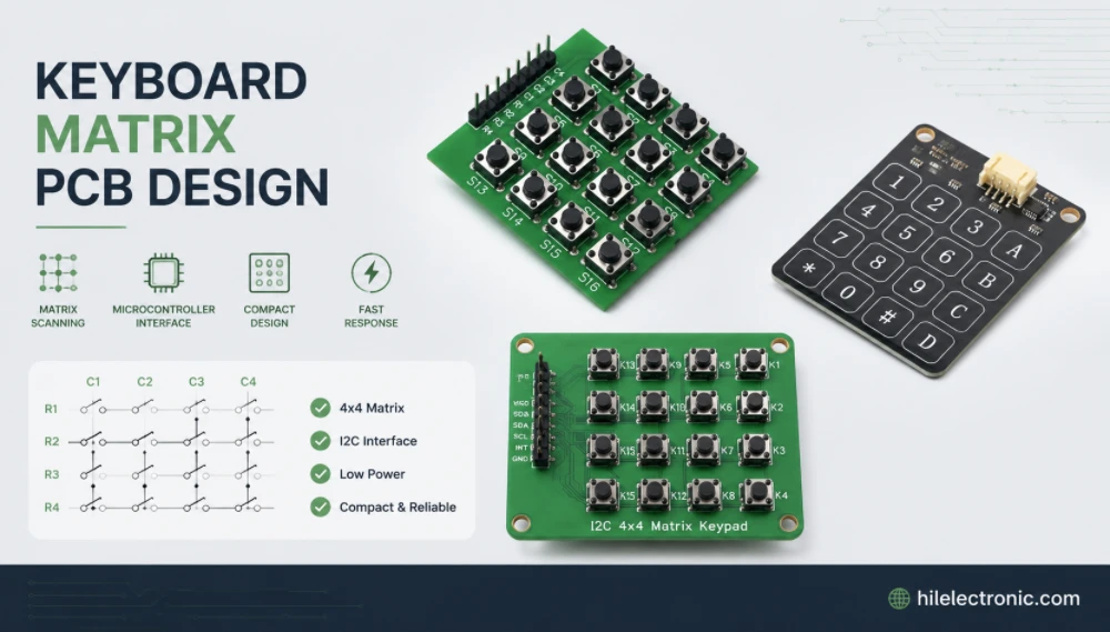
Keyboard Matrix PCB Design & Manufacturing | Anti-Ghosting
Keyboard matrix PCB design converts a large number of...
How to get a quote for PCBs
Let us run DFM/DFA analysis for you and get back to you with a report.
You can upload your files securely through our website.
We require the following information in order to give you a quote:
-
- Gerber, ODB++, or .pcb, spec.
- BOM list if you require assembly
- Quantity
- Turn time
In addition to PCB manufacturing, we offer a comprehensive range of electronic services, including PCB design, PCBA (Printed Circuit Board Assembly), and turnkey solutions. Whether you need help with prototyping, design verification, component sourcing, or mass production, we provide end-to-end support to ensure your project’s success. For PCBA services, please provide your BOM (Bill of Materials) and any specific assembly instructions. We also offer DFM/DFA analysis to optimize your designs for manufacturability and assembly, ensuring a smooth production process.