
Robot Control Board PCB Solutions for Robotics

Robots are built on electronics. Whether you are developing industrial robot arms, AGVs/AMRs, service robots, or quadruped robot dogs, the system’s stability and precision depend on a coordinated set of PCBs: control, perception, sensing, drive, power, communications, safety I/O, and charging/docking accessories. Each board type has different requirements for signal integrity, EMI, thermal performance, mechanical strength, and production testing.
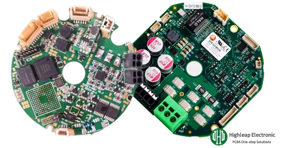
Highleap Electronics is a PCB manufacturing and PCB assembly factory supporting robot control board PCBs and related modules from prototype to mass production. We deliver integrated fabrication and PCBA, plus inspection and functional validation, to help robotics teams achieve consistent quality and stable supply.
Quick Navigation
- Robot Subsystems and PCB Types
- Main Control Board PCB
- Vision and Sensor System PCBs
- Drive and Motion Control PCBs
- Power, Battery, Charging and Accessories PCBs
- Manufacturing, Assembly, Testing and RFQ Checklist
Robot Subsystems and PCB Types
A robot is a system-of-systems. At the electronics level, reliable robots are typically organized into functional subsystems that map to dedicated boards. This modular approach reduces noise coupling, improves thermal management, and makes it easier to scale designs and maintain them in the field.
- Main control (controller board PCB): application compute + real-time control, safety logic, logging, and core interfaces.
- Perception (vision boards): camera interface/carrier boards, high-speed connectors, shielding footprints, and stable power rails.
- Sensing (sensor hub boards): IMU, encoder inputs, ToF/ultrasonic, force/torque sensing, analog conditioning, and sensor fusion interfaces.
- Actuation (drive boards): servo/BLDC motor control, current sensing, protection circuits, braking, and thermal paths.
- Power (power/BMS boards): DC/DC conversion, protection, monitoring, battery management, and charging/docking.
- Communications and I/O: industrial networking front ends, isolated I/O, field wiring interfaces, service/debug ports, and diagnostics.
- Accessories and peripherals: docking stations, remote controllers, teach pendant boards, interface adapters, indicator boards, and small control modules.
Different robot platforms emphasize different modules. Industrial arms often focus on deterministic motion and safety I/O. Mobile robots add battery, charging, and navigation sensing. Robot dogs typically use multiple distributed joint drive boards plus a high-stability sensor hub for gait control, all under vibration and rapid load transients.
Highleap supports these board families with integrated production flow through PCB fabrication and PCB assembly, so design choices stay aligned with what can be built reliably at scale.
Main Control Board PCB
The main control board is the robot’s coordination center. It schedules tasks, executes control loops, manages safety states, handles communications, and distributes commands to drives and peripherals. A strong controller design balances high-performance processing with deterministic real-time behavior.
Typical controller board building blocks
- Application processor domain: runs planning, navigation, and software stacks (commonly Linux/ROS), manages logs and OTA updates.
- Real-time control domain: MCU/real-time controller for tight loops (position/velocity/torque), watchdog functions, and fail-safe actions.
- Memory and storage: high-speed memory interface routing discipline; non-volatile storage for firmware and event logs.
- Timing and synchronization: stable clocking, low-jitter references, and clean power integrity for deterministic control.
- Interface protection: ESD/transient protection and filtering at external connectors and long cable runs.
PCB design priorities that directly impact stability
- Power integrity: PDN planning (bulk + high-frequency decoupling), controlled switching noise, and clean return paths.
- Signal integrity: impedance-controlled routing for high-speed interfaces, length control where required, and continuous reference planes.
- EMI discipline: board zoning, guard/return strategy, and separation between noisy power regions and sensitive clocks/sensors.
- Serviceability and testability: programming headers, test points for key rails, clear labeling, and controlled access areas.
When the controller integrates multiple high-speed links, disciplined routing methods from high-speed PCB design become important. For routing-dense BGAs and compact layouts, many projects adopt HDI PCB manufacturing to improve escape routing, reduce via congestion, and keep critical interconnects short.
Vision and Sensor System PCBs
Perception quality sets the ceiling for robot performance. Vision and sensor boards must preserve weak signals, maintain timing, and avoid noise coupling from power and drives. In real deployments, the failure modes are often practical: connector fatigue, grounding mistakes, EMI pickup, or unstable sensor rails.
Vision system boards
- Camera interface boards: high-speed lanes, controlled impedance, robust connectors, and stable power for imaging devices.
- Vision carrier boards: compute module carrier + I/O breakouts, shielding footprints, and thermal management for sustained workloads.
- Lighting/trigger boards (industrial inspection): synchronized strobe control, protection, and timing accuracy.
If your product uses camera modules or inspection cameras, dedicated build practices can reduce risk and rework. Highleap supports camera-related builds through camera PCB manufacturing.
Sensor hub and mixed-signal boards
- IMU and motion sensing: stable references and vibration-aware placement; clean grounding to protect accuracy.
- Encoder and feedback interfaces: noise-resistant capture and conditioning for precise multi-axis motion.
- ToF/ultrasonic/pressure sensing: analog front-ends with filtering and separation from noisy domains.
- Force/torque sensing: low-level analog measurement with careful routing, shielding strategy, and stable excitation rails.
Flexible interconnect for moving structures
Robots with moving joints, rotating heads, compact gimbals, or tight internal packaging often benefit from flexible interconnect. Using flex PCB assembly or rigid-flex PCB can reduce connector count, improve reliability under repeated motion, and simplify internal routing.
Drive and Motion Control PCBs
Drive boards translate control signals into physical motion. They are typically the highest-stress PCBs in a robot due to high current, fast switching edges, heat density, and vibration. This is true for industrial servo systems and even more demanding for robot dogs, where multiple compact joint drives operate under continuous shock and transient loads.
Common drive board categories
- Servo drive control boards: closed-loop control (position/velocity/torque), encoder feedback, fault management, and protective shutdown.
- BLDC motor controller boards: commutation/FOC control, current sensing, braking behavior, and efficiency optimization.
- Actuator/end-effector boards: grippers, linear actuators, valves, solenoids, tool heads, and peripheral motorized modules.
- Distributed joint boards (robot dogs): multiple compact modules near legs/joints, emphasizing thermal and vibration robustness.
Drive PCB design and build risks to manage
- Switching loop control: minimize high di/dt loops to reduce EMI and ringing; optimize gate driver placement and return paths.
- Current measurement integrity: Kelvin sensing where applicable; route measurement signals away from switching nodes.
- Thermal paths: copper distribution, thermal vias, and mechanical interfaces (heatsinks/pads) matched to real dissipation.
- Protection behavior: overcurrent/overvoltage/thermal protection and predictable fault handling.
- Mechanical strength: reinforced connectors, inductors, and tall components under vibration and handling stress.
For practical drive-board guidance used by many robotics teams, see motor driver PCB. High-power conversion and inverter-style constraints are commonly addressed through power electronics PCB design and build practices.
High-current distribution and copper strategy
Where current density and heat rise are limiting factors, many designs adopt multi-layer current spreading and, when appropriate, heavy copper PCB options to improve thermal robustness and current carrying capability.

Power, Battery, Charging and Accessories PCBs
Robotics performance depends on stable power delivery. Power boards keep compute and sensors stable under transients, protect systems from faults, and enable charging/docking. Mobile robots and robot dogs add strong BMS requirements because gait changes and acceleration events create rapid load variations.
Power and battery PCB types used in robotics
- DC/DC power boards: point-of-load regulators for compute, vision, sensors, and comms with filtering and protection.
- Power distribution boards: fused outputs, current monitoring, connector systems, and controlled return paths.
- Battery management boards: monitoring, protection, balancing, and pack communications via battery management PCB.
- Charging and docking boards: docking contacts, detection circuits, and contactless solutions such as wireless charging PCB.
Accessory and peripheral boards that often ship alongside robots
- Charging docks and adapters: contact boards, protection, and interface control modules.
- Remote controllers/teach pendants: UI input boards, display/indicator boards, and robust connector interfaces.
- I/O expansion modules: isolated inputs, relay/driver outputs, and diagnostic monitoring.
- Gateway/interface boards: networking front ends, protection networks, and wiring harness adapters.
These surrounding electronics must match the same reliability expectations as the robot itself: stable connectors, predictable protection behavior, and repeatable manufacturing quality across batches.
Manufacturing, Assembly, Testing and RFQ Checklist
Robotics products require manufacturable designs and repeatable production processes. Highleap supports integrated delivery from PCB fabrication to PCB assembly, with consolidated procurement and scheduling via turnkey PCB assembly.
PCBA process controls that matter for robotics
- Fine-pitch SMT control: stable paste printing and reflow for BGAs/QFNs and dense controllers.
- Mixed technology assembly: SMT + through-hole for high-current connectors and mechanically stressed parts.
- Thermal interface readiness: heatsinks/pads and keep-outs aligned to layout and mechanical constraints.
- Vibration-aware builds: connector reinforcement strategies and appropriate assembly controls where required.
Inspection and testing for high reliability
- X-ray inspection: verify BGA/QFN solder joints via X-ray inspection.
- ICT electrical coverage: verify components and nets via in-circuit testing (ICT).
- Functional testing (FCT): validate end-use behavior using PCB functional testing.
RFQ checklist for fast, accurate quoting
- PCB data: Gerber/ODB++, drill files, board thickness, copper weight, impedance targets, and stackup requirements.
- BOM: manufacturer part numbers, approved alternates, and any controlled parts requiring traceability.
- Assembly package: pick-and-place file, assembly drawings, polarity notes, and special process requirements.
- Programming and test: firmware loading needs, ICT/FCT requirements, fixtures, and acceptance criteria.
- Environment targets: vibration, temperature range, duty cycle, and any protection/coating requirements.
- Quantity plan: prototype quantity, pilot run, and monthly forecast for stable sourcing and scheduling.

Recommended Posts

Panasonic MEGTRON 7N PCB for AI Server HDI Boards
Panasonic MEGTRON 7N is best understood as a platform...

Ventec VT-481 PCB for Lead-Free Reliability
Ventec VT-481 is a mid-Tg, phenolic-cured FR-4.0 laminate...

TUC TU-872 SLK PCB for High-Speed FR-4 Cost Control
TUC TU-872 SLK occupies a commercially useful middle...

Shengyi S1000-2M PCB for Thick Multilayer Reliability
Shengyi S1000-2M is a high-Tg, low-CTE FR-4.0 laminate for...
How to get a quote for PCBs
Let us run DFM/DFA analysis for you and get back to you with a report.
You can upload your files securely through our website.
We require the following information in order to give you a quote:
-
- Gerber, ODB++, or .pcb, spec.
- BOM list if you require assembly
- Quantity
- Turn time
In addition to PCB manufacturing, we offer a comprehensive range of electronic services, including PCB design, PCBA (Printed Circuit Board Assembly), and turnkey solutions. Whether you need help with prototyping, design verification, component sourcing, or mass production, we provide end-to-end support to ensure your project’s success. For PCBA services, please provide your BOM (Bill of Materials) and any specific assembly instructions. We also offer DFM/DFA analysis to optimize your designs for manufacturability and assembly, ensuring a smooth production process.