
Wireless Charging PCB Manufacturing Guide

Highleap Electronics delivers comprehensive PCB manufacturing and assembly solutions across consumer electronics, automotive, medical, and industrial sectors. Wireless charging PCBs have become a critical specialization as the world moves toward cable-free power. From 5W smartphone pads to 100W automotive systems, we manufacture boards that efficiently transfer power through magnetic fields while meeting strict safety and EMI requirements.
Wireless Charging PCB Resonant Circuit Design
Wireless charging operates through resonant inductive coupling between transmitter and receiver coils. The efficiency depends critically on matching resonant frequencies—even 1% mismatch can reduce power transfer by 20% or cause complete failure.
The resonance equation f = 1/(2π√LC) appears simple, but component tolerances compound:
- Coil inductance varies ±10% with manufacturing
- Capacitance tolerance adds ±5% uncertainty
- Temperature coefficients contribute ±3% drift
- PCB parasitics introduce unpredictable variations
Combined variations can shift resonance ±15%, destroying efficiency. We address this through precision component selection (±1% or better), temperature-stable C0G/NP0 capacitors, trimming capacitor arrays for tuning, and layouts minimizing parasitic effects.
Q-factor determines power transfer efficiency. High-Q coils transfer power with minimal losses. PCB design significantly impacts Q through trace resistance, via placement, ground plane coupling, and proximity effects. Our designs achieve Q-factors exceeding 200 through 3oz minimum copper, optimized via usage, and careful field management techniques refined in our high power density PCB manufacturing.
Wireless Charging PCB Coil Design and Integration
The transmitter coil dominates wireless charger size and performance. Two integration approaches exist, each with distinct trade-offs.
PCB-Embedded Coils: Multi-layer spirals built into the PCB offer perfect repeatability and automated assembly:
- 4-10 layers for optimal inductance
- 3-6oz copper for low resistance
- Optimized width/spacing ratios
- Minimal via interconnections
Challenge: achieving high Q-factor with PCB traces. Copper resistance exceeds Litz wire, and proximity effects between layers increase losses. We optimize through wider outer layer traces where current density peaks and maintain spacing reducing proximity effects.
Wire-Wound Integration: Litz wire coils offer superior Q-factor (>300) but require precise PCB accommodation:
- Routed pockets with ±0.1mm tolerance
- Solder pads for wire termination
- Strain relief preventing mechanical failure
- Ferrite shield alignment features
The PCB becomes a precision platform maintaining coil flatness within 0.1mm for consistent coupling. Our wireless charging PCB manufacturing ensures reliable integration regardless of coil type.
Wireless Charging PCB Safety with Foreign Object Detection (FOD)
Metal objects between charger and device can heat dangerously. Foreign Object Detection (FOD) prevents fires through multiple sensing methods we implement.
Q-Factor Monitoring: Metal objects lower coil Q by absorbing energy. We measure baseline Q at initialization, continuously monitor during charging, detect 5% reductions, and respond within 100ms. This requires precision current sensing (±1%), temperature-stable references, high-speed ADC interfaces, and isolated measurement circuits.
Frequency Shift Detection: Metal objects change effective inductance, shifting resonance. Implementation needs stable oscillator references, precision frequency measurement, and temperature compensation. Our LED driver PCB experience with precision analog circuits ensures accurate detection.
Multi-Coil Arrays: Advanced systems use 8-16 sense coils surrounding the main coil providing spatial detection. These require careful layout preventing cross-coupling while maintaining sensitivity through dedicated layers, shielding between circuits, and matched trace lengths.

EMI Control Techniques in Wireless Charging PCB Design
Wireless chargers are intentional radiators at ISM frequencies (87-205kHz for Qi), but emissions must stay within legal limits. The challenge: transferring 50W magnetically while meeting EMI requirements. Every PCB trace becomes an antenna. At 100kHz, efficiency is poor but harmonics radiate effectively. We control emissions through:
- Minimized trace lengths via optimal placement
- Differential routing canceling radiated fields
- Shield planes containing electromagnetic energy
- Edge plating creating complete Faraday cage
The charging field itself needs shaping. Ferrite sheets direct fields vertically, aluminum shields block stray emissions, and optimized coil geometry concentrates energy where needed. Proper implementation reduces unwanted emissions 20dB while improving power transfer.
Conducted emissions flow back through power supplies. We implement common-mode chokes at input, X/Y capacitor filtering networks, proper ground plane design, and physical separation between noisy and clean sections. These techniques from our switching power PCB expertise ensure compliance.
Efficiency Optimization for Wireless Charging PCBs
Wireless charging inherently loses 10-20% versus wired connections. Superior PCB design minimizes these losses through careful optimization. At 100kHz+, skin effect constrains current to copper surfaces. Skin depth is only 0.2mm, causing effective resistance to increase 2-5x. Current crowds to trace edges while proximity effects compound losses.
Solutions include multiple parallel traces versus single thick paths, optimal conductor spacing, curved routing for gradual current steering, and heavy copper (3-6oz) for critical sections. These techniques proven in our ultra-fast charging PCB designs maximize wireless charging efficiency.
Zero-voltage switching eliminates turn-on losses through precise dead-time control (50-200ns), matched FET characteristics, controlled parasitic capacitance, and optimized gate timing. PCB layout determines ZVS achievement requiring minimal gate loop inductance and balanced parasitics.
FAQ
Q: What is Qi wireless charging standard?
A: Qi is the dominant standard operating at 87-205kHz for up to 15W power transfer. Highleap Electronics manufactures Qi-certified PCBs with precise frequency control, FOD implementation, and protocol compliance ensuring universal device compatibility.
Q: How efficient is wireless charging?
A: Modern wireless charging achieves 75-85% efficiency versus 90-95% for wired. Highleap Electronics maximizes efficiency through optimized coil coupling, high-Q resonant circuits, low-loss materials, and precision component selection consistently achieving top-tier ratings.
Q: What causes wireless chargers to overheat?
A: Heat comes from coil resistance, switching losses, core losses, and transfer inefficiency. Highleap Electronics minimizes heating through thermal vias, metal-core substrates where needed, optimized switching frequencies, and comprehensive thermal modeling during design.
Q: Can wireless charging work through cases?
A: Yes, most cases up to 5mm thickness work fine. Metal cases block magnetic fields completely. Highleap Electronics designs accommodate typical case thickness through optimized coil design and power level adjustment. Our GaN power PCB high-frequency expertise enables efficient power transfer despite gaps.

Related Articles
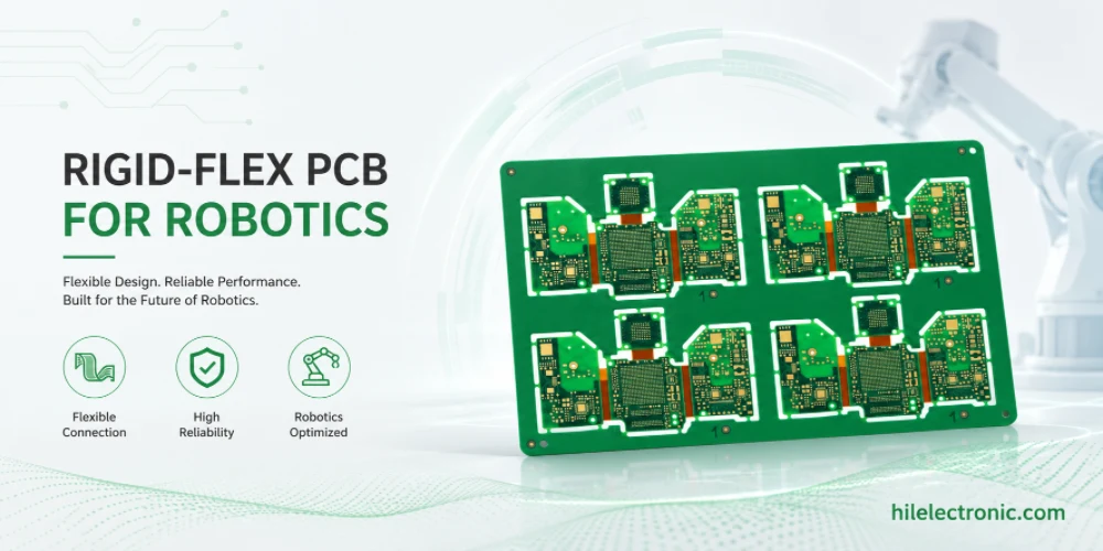
Rigid-Flex PCB for Robotics: Joint Interconnects That Survive Motion
Rigid-flex PCB manufacturing for robotics is valuable when...
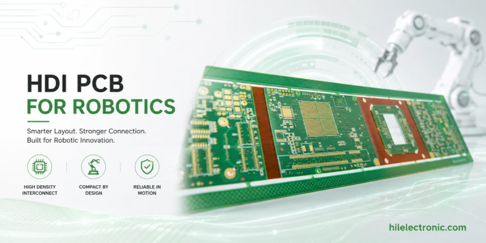
HDI PCB for Robotics: Microvias, BGA Fanout and Signal Integrity
HDI PCB manufacturing for robotics is driven by compact...
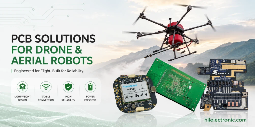
Drone and Aerial Robot PCB for Flight Control and ESC Reliability
Drone and aerial robot PCB manufacturing is shaped by...
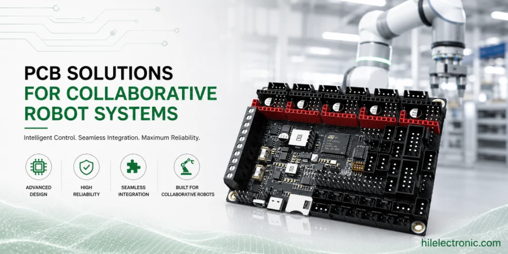
Collaborative Robot PCB for Cobot Safety and Joint Control
Collaborative robot PCBs support robots that operate near...
How to get a quote for PCBs
Let us run DFM/DFA analysis for you and get back to you with a report.
You can upload your files securely through our website.
We require the following information in order to give you a quote:
-
- Gerber, ODB++, or .pcb, spec.
- BOM list if you require assembly
- Quantity
- Turn time
In addition to PCB manufacturing, we offer a comprehensive range of electronic services, including PCB design, PCBA (Printed Circuit Board Assembly), and turnkey solutions. Whether you need help with prototyping, design verification, component sourcing, or mass production, we provide end-to-end support to ensure your project’s success. For PCBA services, please provide your BOM (Bill of Materials) and any specific assembly instructions. We also offer DFM/DFA analysis to optimize your designs for manufacturability and assembly, ensuring a smooth production process.