
Ultra Fast Charging PCB Manufacturing Solutions

Highleap Electronics is a comprehensive PCB manufacturing and assembly company serving automotive, telecommunications, energy, and consumer electronics industries. Among our diverse capabilities, ultra-fast charging PCBs represent the cutting edge of power delivery technology—enabling everything from 100W smartphone chargers to 350kW EV superchargers that redefine charging speed expectations.
Heavy Copper Solutions for Extreme Current Handling
Ultra-fast charging demands current levels that would destroy standard PCBs instantly. A 350kW charger pushes 500+ amps continuously—current that requires revolutionary PCB design approaches to handle safely and efficiently.
We implement heavy copper ranging from 6oz to 20oz thickness, far beyond the 1-2oz used in standard electronics. But manufacturing heavy copper presents unique challenges. Standard etching loses precision with thick copper, creating undercut that weakens traces. Our controlled-depth milling maintains ±10% thickness tolerance even at 20oz weights.
Critical design considerations for high current:
- Multiple parallel paths distribute current load
- Via arrays with 50+ thermal vias under connections
- Current density maintained below 30A/mm²
- Copper balancing prevents board warpage
The difference between success and failure often comes down to proper current distribution. Our EV charging PCB experience directly applies to these extreme current requirements, ensuring reliable operation for decades.
Thermal Management at Kilowatt Scale
At 350kW, even 98% efficiency means 7kW of waste heat—equivalent to seven hair dryers in a space smaller than a laptop. Without exceptional thermal design, components would fail within seconds.
Traditional thermal vias aren’t sufficient at these power levels. We implement comprehensive thermal architectures including copper-wrapped barrels for 3x better conductivity, filled vias eliminating air gaps, and metal-core substrates when FR-4 reaches its limits. Aluminum substrates provide 5W/mK thermal conductivity, while copper substrates deliver 380W/mK—over 1000x better than standard FR-4.
For the most demanding applications, liquid cooling becomes mandatory. We design PCBs with integrated cooling preparation—mounting surfaces for cold plates, thermal interface material optimization, and isolated temperature monitoring circuits. Some advanced designs incorporate cooling channels directly in the PCB structure, though this requires specialized manufacturing capabilities we’ve developed through our high power density PCB projects.
Wide-Bandgap Semiconductors Enable the Revolution
Silicon carbide (SiC) and gallium nitride (GaN) semiconductors transformed ultra-fast charging from laboratory curiosity to commercial reality. These devices switch 10x faster than silicon with dramatically lower losses, enabling the efficiency and power density required for practical ultra-fast charging.
But wide-bandgap devices demand exceptional PCB design. At 50V/ns switching speeds, every millimeter of trace matters. Parasitic inductance that barely affected silicon IGBTs now causes destructive voltage overshoot with SiC and GaN.
Layout optimization for wide-bandgap devices:
- Vertical power loops using adjacent layers
- Via arrays for minimal inductance transitions
- Gate drive traces as controlled impedance lines
- Component placement minimizing loop area
Our GaN power PCB manufacturing expertise guides these critical layout decisions, ensuring stable operation at extreme switching speeds while maintaining efficiency above 98%.

Smart Charging Protocol Integration
Ultra-fast charging isn’t just about raw power delivery—it requires intelligent communication between charger and device. Modern systems support USB Power Delivery Extended Power Range (EPR) up to 240W, proprietary protocols like OPPO’s 150W SuperVOOC, and vehicle-to-grid bidirectional charging.
Each protocol demands specific PCB implementations. USB-PD requires precise impedance control on CC communication lines while isolating them from high-voltage power rails. Proprietary protocols often need encrypted authentication chips and specialized handshake circuits. Our fast charging controller PCB designs seamlessly integrate these diverse requirements.
The PCB must handle high-speed digital communication millimeters from kilowatt-level power switching—an electromagnetic compatibility nightmare. We achieve this through careful layer stackup design, strategic ground plane segmentation, and comprehensive shielding between power and signal domains.
Safety Systems for Extreme Power Levels
At these power levels, safety transcends compliance—it’s fundamental to every design decision. Multiple protection layers prevent catastrophic failures that could endanger users or equipment.
Comprehensive protection implementation:
- Overcurrent detection responding in microseconds
- Arc fault detection for connector problems
- Ground fault interruption within 20ms
- Thermal monitoring at multiple points
- Isolation barriers exceeding 4kV rating
High-voltage spacing becomes critical. For 1000V systems, we maintain 15mm creepage distances—50% above minimum requirements. Physical isolation slots between primary and secondary circuits ensure safety even with contamination or component failure. These design principles, refined through our power module PCB manufacturing, ensure fail-safe operation under all conditions.
Manufacturing Excellence for Reliability
Ultra-fast charging PCBs operate at the edge of what’s physically possible, demanding manufacturing excellence beyond standard electronics.
Every board undergoes comprehensive testing including 100% electrical verification, high-potential isolation testing, thermal cycling validation, and x-ray inspection for hidden defects. We maintain full traceability from raw materials through assembly, supporting the 10+ year warranties these systems require.
Our advanced capabilities include sequential lamination for embedded components, HDI technology for maximum density, and specialized processes for exotic materials. Whether producing prototypes or scaling to thousands of units, we maintain the same exacting standards. This expertise extends across our entire portfolio, from wireless charging PCB to AI data center power PCB applications.
Frequently Asked Questions
Q: What’s the difference between fast charging and ultra-fast charging?
A: Fast charging typically refers to 18–65W for consumer devices, while ultra-fast charging exceeds 100W, reaching 350kW for EVs. Highleap Electronics manufactures PCBs across this entire range, with specialized heavy copper processing and thermal management for the highest power levels.
Q: How long does ultra-fast charging take?
A: Modern ultra-fast charging can charge smartphones to 80% in 10–15 minutes (100W+) or add 200 miles to an EV in 10 minutes (350kW). Highleap Electronics’ PCB solutions enable these remarkable speeds through optimized power delivery and thermal management.
Q: Is ultra-fast charging safe for batteries?
A: Yes, when properly implemented with temperature monitoring, current control, and intelligent charging algorithms. Highleap Electronics integrates comprehensive safety features in every ultra-fast charging PCB, including multi-zone temperature sensing and redundant protection circuits.
Q: What are the main challenges in ultra-fast charging PCB design?
A: Key challenges include managing hundreds of amps of current, dissipating kilowatts of heat, maintaining safety isolation, and supporting multiple charging protocols. Highleap Electronics addresses these through heavy copper expertise, advanced thermal solutions, and proven high-voltage design experience.
Q: Can existing charging infrastructure be upgraded to ultra-fast charging?
A: Rarely—ultra-fast charging typically requires complete redesign due to higher currents, voltages, and thermal requirements. Highleap Electronics helps customers transition from standard to ultra-fast charging through comprehensive design support and manufacturing expertise from our switching power PCB and LED driver PCB experience.

Related Articles
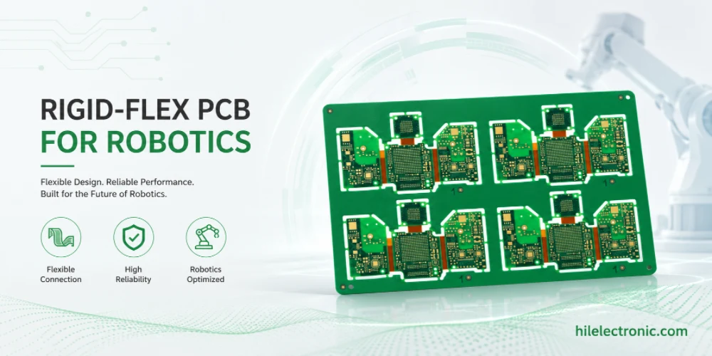
Rigid-Flex PCB for Robotics: Joint Interconnects That Survive Motion
Rigid-flex PCB manufacturing for robotics is valuable when...
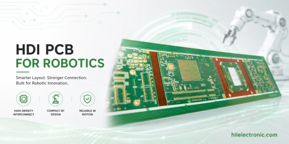
HDI PCB for Robotics: Microvias, BGA Fanout and Signal Integrity
HDI PCB manufacturing for robotics is driven by compact...
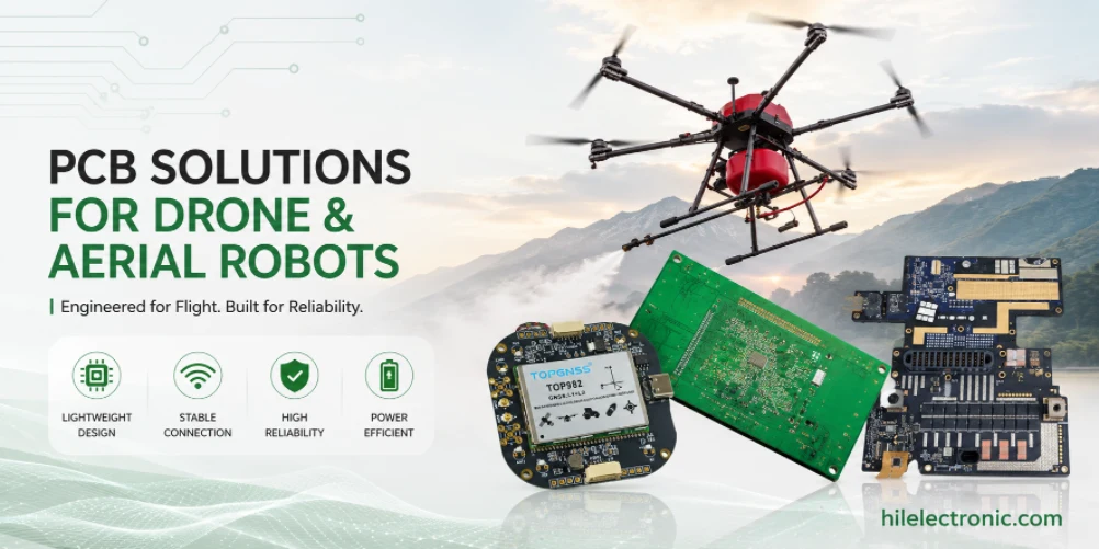
Drone and Aerial Robot PCB for Flight Control and ESC Reliability
Drone and aerial robot PCB manufacturing is shaped by...
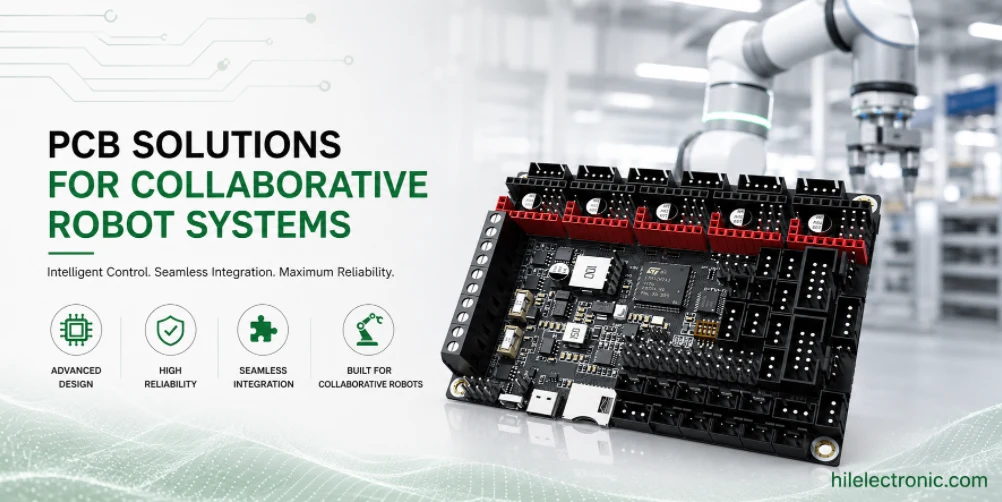
Collaborative Robot PCB for Cobot Safety and Joint Control
Collaborative robot PCBs support robots that operate near...
How to get a quote for PCBs
Let us run DFM/DFA analysis for you and get back to you with a report.
You can upload your files securely through our website.
We require the following information in order to give you a quote:
-
- Gerber, ODB++, or .pcb, spec.
- BOM list if you require assembly
- Quantity
- Turn time
In addition to PCB manufacturing, we offer a comprehensive range of electronic services, including PCB design, PCBA (Printed Circuit Board Assembly), and turnkey solutions. Whether you need help with prototyping, design verification, component sourcing, or mass production, we provide end-to-end support to ensure your project’s success. For PCBA services, please provide your BOM (Bill of Materials) and any specific assembly instructions. We also offer DFM/DFA analysis to optimize your designs for manufacturability and assembly, ensuring a smooth production process.