
PCB Cable Assembly: Types, Design & Manufacturing Guide

1. Introduction to PCB Cable Assembly
Modern electronic systems rely on printed circuit boards (PCBs) and their associated components to function. However, the interconnection between circuit boards or between boards and external devices depends critically on cable assemblies. These assemblies serve as the nervous system of electronic products, ensuring reliable transmission of power, signals, and control information across various modules.
This guide provides a detailed examination of PCB cable assembly fundamentals, types, design specifications, manufacturing processes, and quality assurance methods.
2. What Is PCB Cable Assembly
A PCB cable assembly consists of multiple wires or cables organized within a protective sheath, terminated with specific connectors at both ends. These assemblies facilitate power and signal transmission between PCBs and their peripheral components.
The primary constituents include conductor wires (single or multi-core configurations), insulation sheaths made from materials such as PVC, TPE, or fluorocarbon compounds, and connectors or terminals designed for reliable mating with PCBs or equipment interfaces.
PCB cable assemblies perform three essential functions: organizing structured connections to reduce cable clutter, providing environmental protection against heat, friction, moisture, and mechanical stress, and facilitating straightforward installation and maintenance procedures.
3. Types of PCB Cable Assembly
3.1 Audio/Video (AV) Cables
AV cable assemblies transmit audio and video signals between devices. These cables require excellent shielding properties and low impedance characteristics to maintain signal integrity. Proper construction prevents signal degradation and electromagnetic interference during transmission.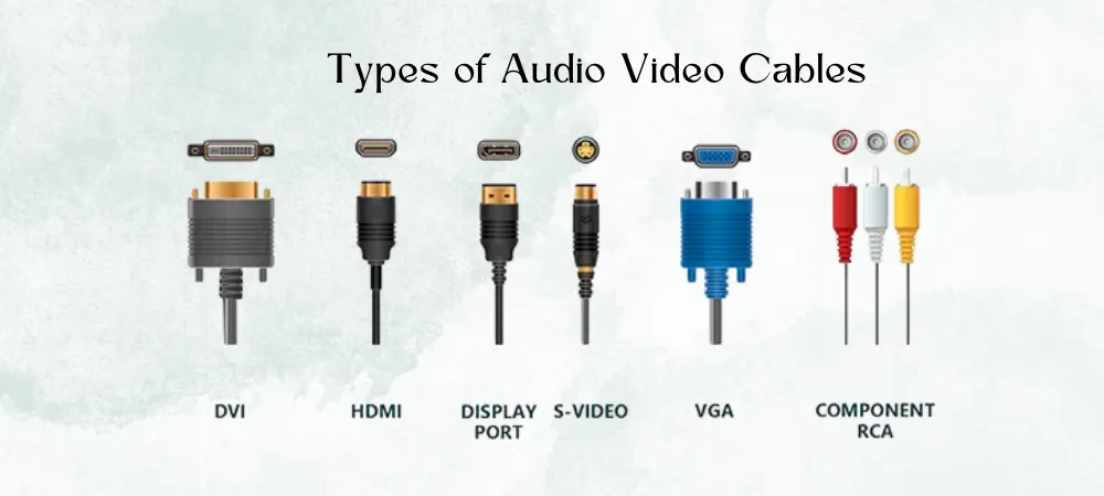
3.2 Flat Ribbon Cables
Flat ribbon cable assemblies feature multiple parallel conductors arranged in a planar configuration. This design enables compact connections between PCBs in space-constrained applications. The flat profile allows efficient routing through tight enclosures while maintaining organized conductor spacing.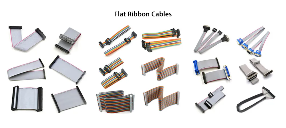
3.3 Molded Cable Assemblies
Molded cable assemblies incorporate injection-molded terminations that enhance mechanical durability and environmental resistance. The overmolded ends provide superior protection against impact forces, strain, and environmental stresses compared to standard termination methods.
3.4 EMI/RF Shielded Cables
Shielded cable assemblies incorporate metallic shielding layers to mitigate electromagnetic interference (EMI) and support high-frequency signal transmission. These assemblies are essential in applications where signal integrity must be preserved in electrically noisy environments.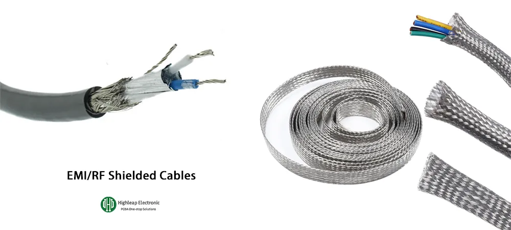
3.5 Other Cable Types
Additional PCB cable assembly categories include power cables designed for current delivery, signal cables optimized for data transmission, and multi-core combination cables that integrate multiple conductor types. Selection depends on specific application requirements and electrical parameters.
4. Technical Specifications for PCB Cable Assembly
4.1 Electrical Performance Parameters
Voltage and current ratings determine the maximum electrical load a cable assembly can safely handle without thermal damage. Impedance matching is critical for signal cables to minimize reflections and insertion losses. Voltage drop calculations, based on conductor gauge (AWG) and cable length, must satisfy system requirements.
4.2 Physical and Environmental Specifications
Insulation and sheath materials affect temperature tolerance, moisture resistance, and mechanical strength. Operating temperature ratings must match deployment environments. IP protection ratings indicate resistance to dust and liquid ingress, determining suitability for harsh operating conditions.
4.3 Mechanical and Geometric Design
Wire gauge selection, minimum bend radius constraints, connector types (push-pull, threaded, or latching), and shielding configurations constitute critical mechanical design factors. Cable harness management practices ensure organized routing and prevent mechanical stress on terminations.

5. PCB Cable Assembly Manufacturing Process
5.1 Design Engineering
Manufacturing begins with engineering analysis to determine cable types, lengths, terminal specifications, and insulation materials based on electrical and mechanical requirements. Design documentation establishes all parameters before production commences.
5.2 Cable Preparation
Preparation involves cutting cables to precise lengths, stripping insulation from conductor ends, and applying tinning or other surface treatments. Accurate preparation ensures consistent termination quality across production batches.
5.3 Terminal and Connector Assembly
Terminal attachment methods include crimping, soldering, and insulation displacement connection (IDC). Method selection depends on connector specifications, production volume requirements, and reliability standards for the target application.
5.4 Wire Harness Organization
Multiple wires are combined, twisted, bundled, or enclosed in protective conduits to form organized harnesses. Proper harness construction maintains conductor positions, facilitates installation, and protects against mechanical damage.
5.5 Overmolding and Heat Shrink Application
Critical junction points receive overmolding or heat shrink tubing to enhance durability and environmental protection. These processes seal terminations against moisture ingress and provide strain relief at high-stress connection points.
5.6 Labeling and Identification
Cable assemblies receive labels indicating function, pin assignments, and identification codes. Clear marking facilitates correct installation, simplifies troubleshooting, and supports efficient maintenance procedures.
If this requirement affects sourcing or production release, compare it with PCB manufacturing capability and turnkey PCBA service before sending the final files for review.
6. Quality Testing and Verification
6.1 Electrical Testing
Continuity testing verifies conductor connections, while insulation resistance measurements confirm dielectric integrity. Signal integrity testing validates performance in EMI-sensitive or high-frequency applications, ensuring compliance with transmission specifications.
6.2 Mechanical and Environmental Testing
Temperature cycling tests evaluate thermal stability across operating ranges. Flex fatigue testing assesses durability under repeated bending. Liquid ingress testing confirms IP rating compliance and validates environmental sealing effectiveness.
6.3 Visual and Dimensional Inspection
Physical inspection confirms that assemblies match engineering drawings regarding dimensions, connector positioning, and workmanship standards. Visual examination identifies defects in crimping, soldering, or insulation that could compromise reliability.
7. Common PCB Cable Assembly Design Mistakes
7.1 Overlooking Electrical Parameter Evaluation
Insufficient attention to AWG selection and impedance requirements leads to performance failures. Always calculate current capacity and verify impedance matching before finalizing cable assembly specifications.
7.2 Ignoring Environmental Factors
Failure to consider operating temperature, humidity, and chemical exposure results in premature degradation. Select materials and protection methods appropriate for actual deployment conditions.
7.3 Connector Mismatch Issues
Incompatible connector selections cause assembly difficulties and unreliable connections. Verify connector compatibility with mating interfaces and confirm mechanical fit during the design phase.
7.4 Improper Bend Radius Design
Exceeding minimum bend radius specifications causes conductor damage and insulation failure. Incorporate routing constraints that respect cable flexibility limits throughout the installation path.
8. Summary
PCB cable assemblies constitute essential interconnection components within electronic systems, enabling reliable power and signal transmission between circuit boards and external devices.
When cable assemblies are part of a complete electronics build, connect the cable drawing with wire harness assembly requirements, turnkey box build assembly, and the final PCB assembly process so the board, harness, enclosure, and test plan are quoted together.
Successful implementation requires understanding cable assembly types and their applications, adherence to electrical, physical, and mechanical specifications, controlled manufacturing processes from design through labeling, and comprehensive quality testing protocols. Engineers and procurement specialists benefit from systematic evaluation of these factors when specifying PCB cable assemblies for their applications.

Recommended Posts
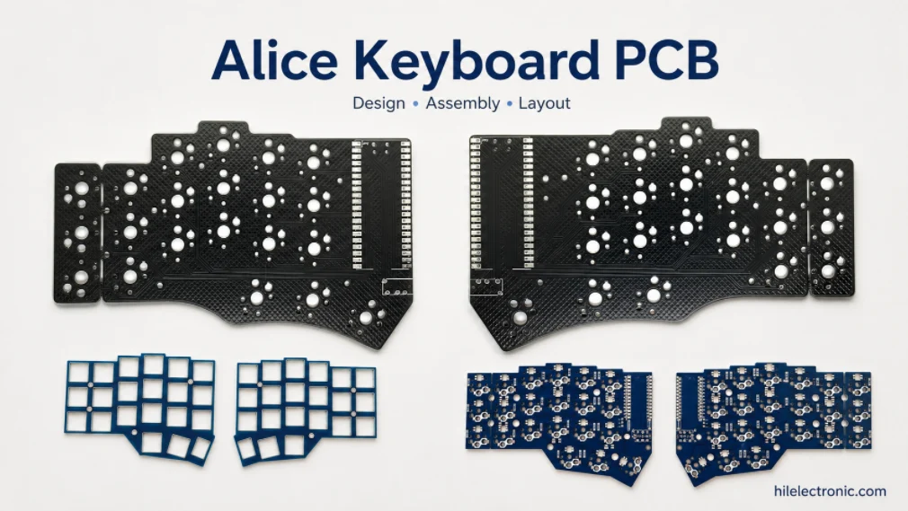
Alice Keyboard PCB Manufacturer | Custom Ergonomic Layout
An Alice keyboard PCB manufacturer must translate an...
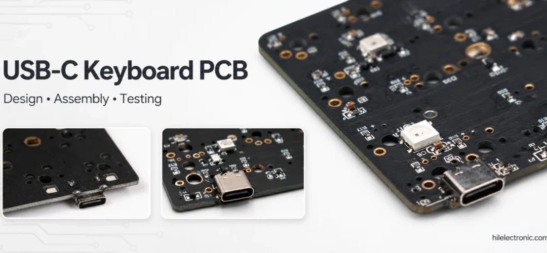
USB-C Keyboard PCB Manufacturer | ESD & Power Protection
A USB-C keyboard PCB manufacturer must control the...

Per-Key RGB Keyboard PCB Manufacturer & LED Assembly
A per-key RGB keyboard PCB manufacturer must control far...

Ortholinear Keyboard PCB Manufacturer | Custom Grid Layout
An ortholinear keyboard PCB manufacturer must preserve a...
How to get a quote for PCBs
Let‘s run DFM/DFA analysis for you and get back to you with a report. You can upload your files securely through our website. We require the following information in order to give you a quote:
-
- Gerber, ODB++, or .pcb, spec.
- BOM list if you require assembly
- Quantity
- Turn time
In addition to PCB manufacturing, we offer a comprehensive range of electronic services, including PCB design, PCBA, and turnkey solutions. Whether you need help with prototyping, design verification, component sourcing, or mass production, we provide end-to-end support to ensure your project’s success.
For PCBA services, please provide your BOM (Bill of Materials) and any specific assembly instructions. We also offer DFM/DFA analysis to optimize your designs for manufacturability and assembly, ensuring a smooth production process.