
Aluminum Solar Inverter PCB Solutions for Power Systems

Introduction
Solar inverters serve as the critical bridge between photovoltaic arrays and electrical grids, converting direct current into usable alternating current. The core challenge lies in managing high power density under continuous operation, particularly in outdoor installations where ambient temperatures can exceed 70°C.
The solar inverter PCB must simultaneously handle high current loads, dissipate substantial heat, and maintain electrical integrity across thousands of operating hours. Aluminum PCB provides a reliable thermal pathway for power management and efficiency stability, addressing the fundamental limitations of traditional circuit board materials.
Understanding Solar Inverter PCB Architecture
Core Components and Thermal Challenges
Modern solar inverters comprise power conversion modules, control circuits, gate driver stages, and integrated thermal management structures. The power stage PCB bears the most critical responsibility, supporting high-current pathways while enabling precise switching control through IGBTs or MOSFETs operating at frequencies between 10 and 50 kHz.
Traditional FR4 substrates struggle in these applications due to poor thermal conductivity of 0.3 to 0.4 W/m·K, which creates localized hot spots around power semiconductors. The mismatch in coefficient of thermal expansion between copper traces and FR4 laminate induces mechanical stress during thermal cycling, leading to solder joint fatigue and premature failure.
Power Density Requirements
Solar inverter PCB designs require careful consideration of both electrical and thermal domains. Power traces must carry currents exceeding 50 amperes while maintaining voltage isolation between high-voltage DC inputs and AC outputs. String inverters and central inverters achieve power densities approaching 5 to 10 watts per square centimeter, necessitating advanced substrate technologies beyond conventional multilayer boards.
Why Aluminum PCB for Solar Inverter Applications
Superior Thermal Performance
The aluminum PCB for solar inverter applications fundamentally changes thermal management dynamics through its metal core construction. An aluminum base layer, typically 1.0 to 3.0 millimeters thick, achieves thermal conductivity between 120 and 200 W/m·K—representing a 400-fold improvement over standard FR4. The dielectric insulation layer maintains electrical isolation while permitting efficient heat flow perpendicular to the board surface.
Key thermal advantages include:
- Rapid heat extraction – Metal core conducts heat 400 times faster than FR4 substrates.
- Uniform temperature distribution – Eliminates hot spots across the power management aluminum PCB surface.
- Reduced junction temperatures – Maintains semiconductor operation 20-30°C cooler than equivalent FR4 designs.
- Enhanced cycling capability – Withstands 100,000+ thermal cycles in accelerated testing protocols.
Mechanical Stability and Reliability
Aluminum exhibits a coefficient of thermal expansion closely matched to copper, reducing stress at solder interfaces during temperature cycling between -40°C and 125°C. This thermal compatibility significantly extends component lifetime in field installations where daily temperature swings impose repetitive mechanical strain on the high power aluminum PCB assembly.
The rigid aluminum substrate provides superior dimensional stability compared to organic laminates, maintaining precise component positioning and trace geometry under thermal load. Environmental robustness further distinguishes these boards, as aluminum naturally resists moisture absorption and maintains electrical properties across humidity extremes.

Solar Inverter PCB
Design Specifications for Power Management Aluminum PCB
Dielectric Layer Engineering
The insulation layer between copper circuitry and aluminum base requires precise engineering to balance thermal performance against electrical safety. Standard dielectric materials achieve thermal conductivity between 1.0 and 1.5 W/m·K at thicknesses of 75 to 150 micrometers. The thermal management PCB for solar inverter applications must maintain dielectric breakdown voltage exceeding 3000 VAC to ensure safe operation with high-voltage DC busses.
Copper and Surface Treatment
Heavy copper construction becomes essential for current-carrying capacity in solar inverter applications. Circuit designers typically specify 2 oz to 4 oz copper weight, corresponding to finished thicknesses between 70 and 140 micrometers. These substantial copper layers accommodate continuous currents exceeding 40 amperes per millimeter of trace width while limiting resistive heating.
Surface finish options ensure reliable connectivity:
- ENIG (Electroless Nickel Immersion Gold) – Provides flat surface for fine-pitch components and multiple reflow cycles.
- OSP (Organic Solderability Preservative) – Cost-effective solution for single-assembly processes with excellent solderability.
- Immersion Silver – Balances performance and cost for high-reliability solar inverter PCB manufacturing.
Thermal Interface Design
Effective heat transfer requires direct thermal paths from component pads to the aluminum base. Design rules must minimize dielectric material beneath high-power device footprints, utilizing thermal vias or direct copper-to-aluminum bonds where possible. Selective thinning of the dielectric layer under critical components can reduce local thermal resistance by 30 to 50 percent.
Electrical Isolation Requirements
High-voltage operation demands rigorous attention to creepage and clearance distances. Power traces carrying 600 to 1000 VDC require minimum spacing of 4 to 6 millimeters from grounded aluminum cores, accounting for pollution degree and altitude factors per IEC standards. Testing protocols verify isolation resistance exceeding 100 megohms and hipot integrity at twice the working voltage plus 1000 volts.
Thermal Reliability in Solar Inverter PCB Systems
Field Performance and Longevity
Aluminum substrate construction directly influences mean time between failures in deployed inverter systems. By maintaining junction temperatures below critical thresholds, metal-core boards reduce semiconductor degradation rates and extend operational lifetimes. This reliability translates to sustained inverter efficiency above 97 percent under continuous operation at 70°C ambient temperature.
Field performance data from utility-scale installations confirms these advantages. Solar farms operating in desert climates with daytime ambient temperatures exceeding 50°C report minimal efficiency degradation when utilizing high power aluminum PCB technology. The superior thermal management prevents efficiency rollback during peak generation hours, maximizing energy harvest when solar irradiance reaches its daily maximum.
Testing and Validation
Power cycling capability improves substantially with aluminum-based modules demonstrating stable performance through extended thermal testing. Maintenance intervals extend accordingly, as thermally stressed components exhibit lower failure rates and reduced degradation over time in production solar inverter PCB assemblies.
Application Examples and Industry Trends
Current Deployment Scenarios
Solar inverter manufacturers deploy aluminum PCB technology across multiple subsystems. The main power conversion board houses the switching transistors, bus capacitors, and filter inductors in string inverters rated from 3 to 300 kilowatts. DC-DC converter stages for maximum power point tracking similarly benefit from aluminum substrates, particularly in high-voltage battery storage systems.
Emerging Technologies
Industry development trends indicate continued substrate evolution:
- Hybrid constructions – Combining aluminum cores with copper heat spreaders for thermal performance beyond 5 W/m·K.
- Advanced dielectrics – Incorporating boron nitride or aluminum oxide fillers to reach 3.0 W/m·K or higher conductivity.
- Manufacturing automation – Reducing costs through optimized processes while maintaining quality standards.
- Lightweight designs – Balancing thermal performance with system-level weight reduction for rooftop installations.
These developments position metal-core technology as the standard solution for next-generation power electronics in renewable energy applications, ensuring solar inverter PCB designs meet increasing power levels and efficiency expectations.
Conclusion
The transition to aluminum-based circuit boards represents a fundamental advancement in solar inverter design, addressing thermal challenges inherent in high-power photovoltaic systems. Metal-core construction provides the thermal conductivity, mechanical stability, and power density required for reliable operation across demanding environmental conditions. As renewable energy installations continue expanding globally, robust power electronics become increasingly critical to grid stability and energy system economics.
Highleap Electronics delivers comprehensive aluminum PCB solutions:
- Custom engineering support – Optimized thermal and electrical design for specific inverter architectures and power ratings.
- Advanced manufacturing capabilities – Metal core PCB production from prototype through high-volume manufacturing with strict quality control.
- Material expertise – Selection and validation of dielectric systems, copper weights, and surface treatments for maximum reliability.
- Testing and validation – Thermal analysis, power cycling, and environmental qualification to meet industry standards.
Contact our technical specialists to discuss your solar inverter PCB requirements and explore how advanced substrate technology can enhance your product performance and field reliability.

Recommended Posts
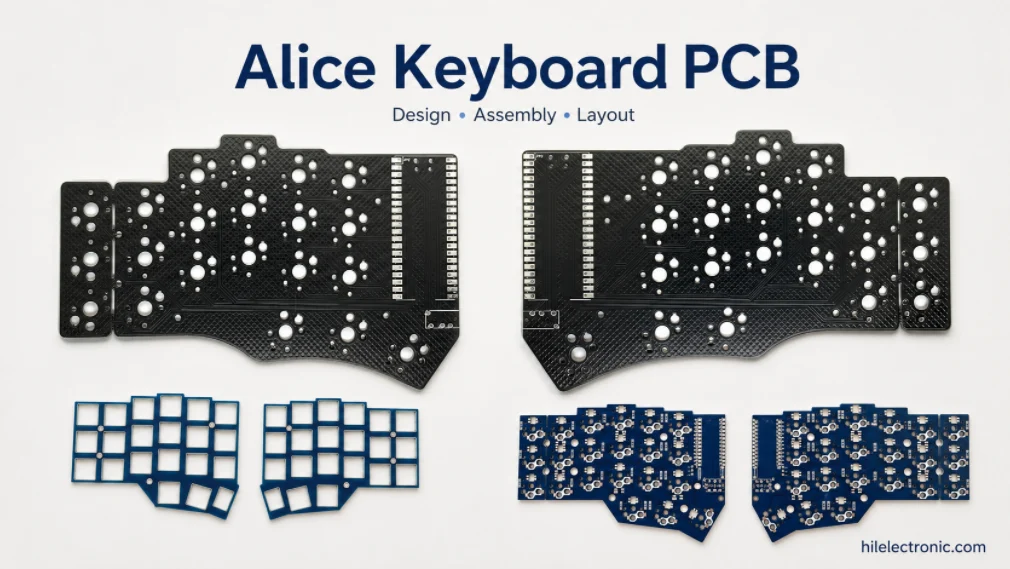
Alice Keyboard PCB Manufacturer | Custom Ergonomic Layout
An Alice keyboard PCB manufacturer must translate an...
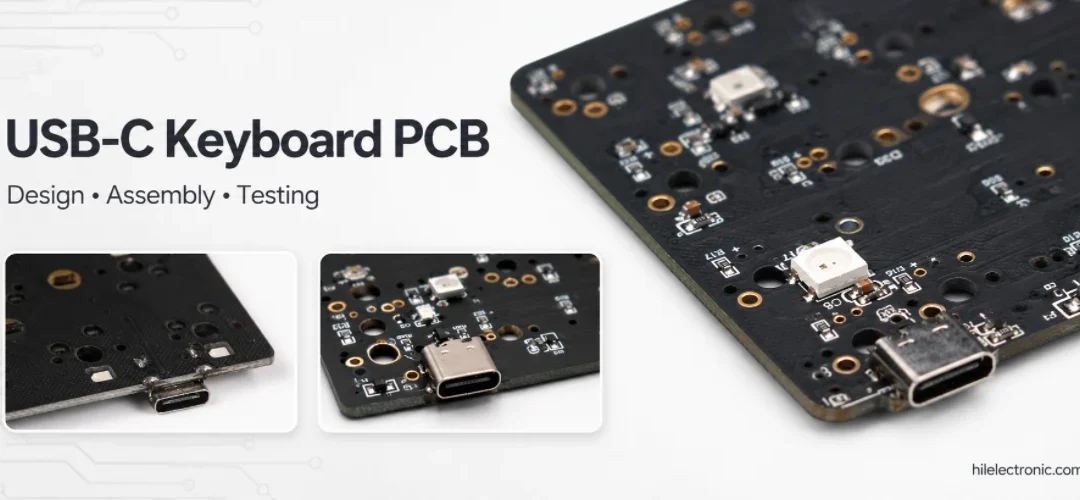
USB-C Keyboard PCB Manufacturer | ESD & Power Protection
A USB-C keyboard PCB manufacturer must control the...

Per-Key RGB Keyboard PCB Manufacturer & LED Assembly
A per-key RGB keyboard PCB manufacturer must control far...

Ortholinear Keyboard PCB Manufacturer | Custom Grid Layout
An ortholinear keyboard PCB manufacturer must preserve a...
How to get a quote for PCBs
Let‘s run DFM/DFA analysis for you and get back to you with a report. You can upload your files securely through our website. We require the following information in order to give you a quote:
-
- Gerber, ODB++, or .pcb, spec.
- BOM list if you require assembly
- Quantity
- Turn time
In addition to PCB manufacturing, we offer a comprehensive range of electronic services, including PCB design, PCBA, and turnkey solutions. Whether you need help with prototyping, design verification, component sourcing, or mass production, we provide end-to-end support to ensure your project’s success.
For PCBA services, please provide your BOM (Bill of Materials) and any specific assembly instructions. We also offer DFM/DFA analysis to optimize your designs for manufacturability and assembly, ensuring a smooth production process.