
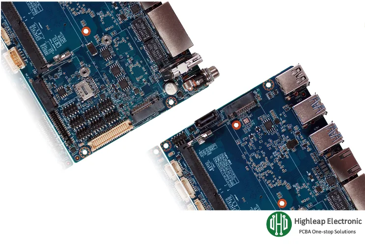
Build a Production-Ready Robot Vision PCB

This article focuses on PCB-level decisions that directly determine perception stability: stackup and materials, high-speed routing and return paths, PDN/EMI strategy, thermal construction, manufacturability, and validation. For teams that want fabrication and assembly to remain aligned with these performance margins through prototyping and volume, our scope is summarized in robot PCB manufacturing and assembly services.
Table of Contents
- System Budgets: Workload, Latency, and “What Must Never Jitter”
- PCB Stackup & Materials: The Foundation for High-Speed and DDR
- Sensor Interfaces: MIPI / USB3 / GigE and Return-Path Discipline
- DDR & Storage: Bandwidth Budgeting and Timing Reality
- Power Integrity & EMI: Keeping Inference Stable Under Motor Noise
- Thermal Design: Sustained Inference Without Throttling
- DFM/DFA: Designing for Repeatable Assembly and Field Robustness
- Validation & Test: Proving Link Margin and Latency in Production
1) System Budgets: Workload, Latency, and “What Must Never Jitter”
Before choosing an AI module or routing a single lane, define budgets that translate into PCB constraints. Vision performance is not just FPS—it is the latency distribution under worst-case scenes and sustained runtime.
- Workload definition: detection < classification < segmentation < 6-DoF pose < dense depth + tracking. Each step raises memory traffic and compute duty cycle, impacting both PDN and thermal design.
- End-to-end latency: include exposure/readout, transfer, pre-processing, inference, post-processing, and transport to the motion controller. Specify p95/p99 targets, not only averages.
- Deterministic boundaries: decide which outputs close a control loop (must be bounded and time-stamped) versus which are “monitoring/logging” (can be best-effort).
- Environmental assumptions: lighting variation, vibration blur, dust, ambient temperature, and EMI from motor drives should be explicit inputs, not afterthoughts.
A practical deliverable is a one-page budget sheet listing camera count, resolution/FPS, target model(s), p95/p99 latency limit, continuous runtime, enclosure constraints, and max power. This prevents the most common failure mode: designing for demo conditions rather than robot conditions.
2) PCB Stackup & Materials: The Foundation for High-Speed and DDR
For vision processing boards, stackup is not a mechanical detail—it is an electrical requirement. MIPI/USB3/PCIe/DDR all depend on controlled impedance, stable reference planes, and predictable dielectric properties. If the stackup is unstable, your eye margins and timing margins will be unstable.
- Stackup defined by interfaces: decide which layers carry high-speed lanes, which layers serve as uninterrupted references, and where the DDR topology lives. This prevents later compromises that create return-path discontinuities.
- Material selection beyond Tg: for high-speed, consistent Dk/Df and their temperature behavior matter. Variability shows up as link margin shrink and timing drift across temperature and builds.
- Impedance control that is actually manufacturable: target impedance must map to achievable trace geometry and tolerance bands. “100Ω diff” is meaningless unless it is tied to controlled dielectric thickness and process capability.
High-density routing and stable impedance often require HDI construction. If your design uses tight pitch BGAs, dense breakouts, or short high-speed channels, review HDI circuit board structures early so the stackup supports routing with margin rather than forcing compromises later.
3) Sensor Interfaces: MIPI / USB3 / GigE and Return-Path Discipline
Intermittent vision failures in robots are frequently caused by signal/return-path issues rather than “camera firmware.” The PCB must preserve channel integrity under EMI, vibration, and temperature.
- MIPI CSI-2 signal integrity: multi-lane differential links require controlled impedance, tight skew, and continuous references. The most common mistake is not the differential pair itself, but the return path being broken by plane splits, voids, or poorly stitched transitions.
- Connector and flex as part of the channel: board-to-FPC connectors, mezzanine connectors, and cable assemblies add discontinuities. Treat them as part of the channel budget, not “outside PCB scope.”
- USB3 / GigE tradeoffs: they enable longer distances and flexible camera placement but increase exposure to common-mode noise and ESD. Layout, shielding/bonding intent, and protection placement must be defined so you don’t “protect the port” by destroying margin.
- Multi-camera synchronization: if you need stereo or multi-view consistency, hardware triggers and matched routing reduce drift compared to software-only sync under CPU/GPU load.
4) DDR & Storage: Bandwidth Budgeting and Timing Reality
Vision workloads become memory-bound quickly. Frame buffers, weights, and activations compete for bandwidth, causing latency spikes even when compute looks sufficient. DDR is also one of the most margin-sensitive parts of the PCB.
- Bandwidth budget: calculate aggregate reads/writes for ingress frames, pre-processing, inference activations, and outputs. Add margin for worst-case scenes and multi-camera bursts.
- DDR is timing engineering: it is not only length matching. Reference continuity, via structures, layer transitions, and placement topology determine whether timing holds across temperature and build variation.
- Prototype vs volume: a DDR link that “passes at room” can become intermittent after assembly variance or at temperature extremes—exactly the conditions robots face.
- Storage strategy affects behavior: eMMC/flash simplifies boot and reduces I/O complexity; NVMe increases throughput and logging capability but adds routing/power/thermal load.
For a production-ready approach to layer planning, via strategy, and tolerance-aware design, use HDI stackup design guide for production-ready PCBs as a baseline when DDR and high-speed interfaces must remain stable through scaling.
5) Power Integrity & EMI: Keeping Inference Stable Under Motor Noise
Robots are electrically hostile: motor drives and DC/DC converters inject broadband noise, ground potentials shift under load, and battery voltage sags during acceleration and braking. A vision PCB must remain stable through these events or inference becomes intermittent.
- PDN impedance targets: AI accelerators create fast load transients. If the PDN impedance is too high at the wrong frequencies, symptoms include resets, throttling, link errors, or “random” inference instability.
- Decoupling by frequency bands: combine high-frequency local decoupling with mid-frequency bulk and rail-level energy storage. Layout must minimize loop inductance, not just place capacitors “nearby.”
- Domain separation with real return planning: separate noisy domains (high-current converters, motor-related rails) from sensitive domains (camera analog/clock/reference). The key is controlling where return currents flow.
- Clock and sensor noise immunity: reference clock distribution and sensor interfaces are often the first victims of common-mode noise. Stitching strategy, chassis bonding intent, and connector shell treatment must be consistent.
6) Thermal Design: Sustained Inference Without Throttling
Thermal design is where “benchmark success” turns into “field failure.” If the board throttles after minutes, latency distributions shift and the robot’s motion assumptions break.
- Design for sustained worst-case: validate in the final enclosure and ambient range, not on an open bench.
- Heatsink attachment consistency: mounting pressure, flatness, and vibration robustness change thermal resistance and unit-to-unit behavior.
- PCB heat spreading: thermal via arrays, internal planes, and controlled copper distribution reduce hotspots, but they must be manufacturable and reliable through thermal cycling.
- Thermal-mechanical interaction: warpage stresses BGAs and fine-pitch joints; thermal expansion under long runtime can become an intermittent fault source if margins are small.
7) DFM/DFA: Designing for Repeatable Assembly and Field Robustness
A vision processing PCB is typically a dense mixed-signal assembly: BGAs, high-speed connectors, sensitive clocks, and high-current rails sharing a constrained footprint. DFM/DFA should explicitly protect the margins you depend on.
- BGA/QFN assembly windows: stencil strategy, reflow profile, and void control influence both power integrity and thermal performance. Small differences can become large latency or stability differences.
- Connector reinforcement for robots: camera FPC connectors, rugged I/O, and board-to-board connectors must survive vibration and handling. Mechanical support and strain relief should be planned, not improvised.
- Cleanliness and coating boundaries: if conformal coating or special cleaning is needed, define keepouts around connectors and thermal interfaces so reliability improves rather than regresses.
- Stackup/impedance control tied to fab execution: high-speed success requires fabrication discipline on layer thickness, copper, and registration—not only design intent.
In robotics programs, this is where capabilities in PCB fabrication and PCB assembly matter in a non-marketing, engineering sense: they determine whether the same impedance, BGA quality, and connector robustness you validated in prototypes can be reproduced consistently in volume.
8) Validation & Test: Proving Link Margin and Latency in Production
For robot vision boards, “boots and runs a demo” is not a production test. Validation must prove the exact failure modes that cause field instability: link margin collapse, DDR intermittency, thermal throttling, and latency jitter.
- High-speed interface validation: qualify camera links, DDR, and high-speed I/O under EMI stress and temperature extremes. Where practical, measure margin (BER-style tests, stress patterns, controlled perturbations) rather than only pass/fail at room.
- Sustained workload thermal validation: run representative models continuously and confirm no throttling and no timing drift in worst-case ambient and enclosure conditions.
- End-of-line functional test: feed deterministic image vectors and verify outputs and timing limits (p95/p99), not only “inference works.”
- Traceable evidence: record firmware/model versions, thermal conditions, and performance counters per unit so field issues can be isolated quickly.
When long duty cycles and harsh environments are part of the real requirement, reliability screening and validation methods should be planned alongside the PCB design. Our reliability testing reference summarizes common approaches used to confirm margin across thermal cycling and other stress conditions.
Summary: A robot vision processing PCB is a real-time AI inference platform. Field-stable perception depends on (1) stackup and material stability, (2) high-speed channel and return-path discipline, (3) PDN/EMI resilience under motor noise, (4) sustained thermal headroom, (5) DFM/DFA that protects margins in assembly, and (6) validation that measures link margin and latency distributions—not just average FPS.

Recommended Posts
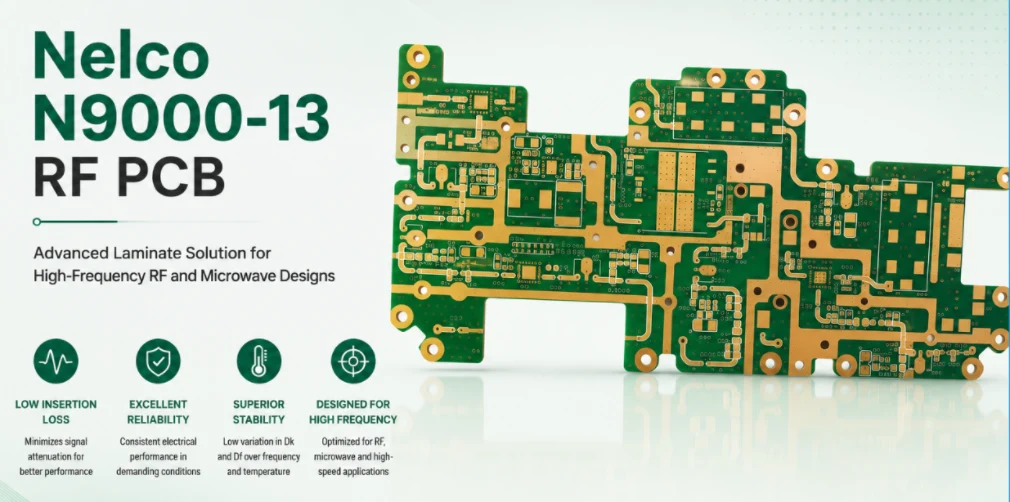
Nelco N9000-13 RF PCB Legacy Manufacturing and Replacement Service
Table of contentsCan Highleap Still Build a Nelco N9000-13...
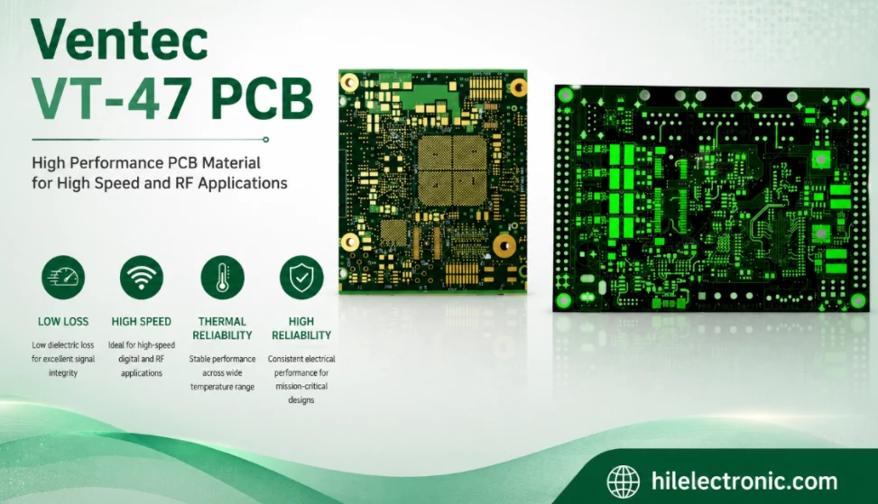
Ventec VT-47 PCB Manufacturer for Reliable High-Tg FR-4 Multilayers
Table of contentsIs Ventec VT-47 the Right High-Tg FR-4...
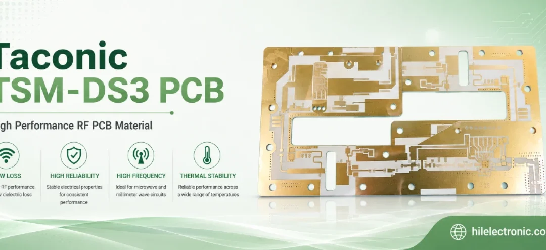
Taconic TSM-DS3 PCB Manufacturer for Thermally Stable RF Multilayers
Table of contentsWhen TSM-DS3 Is the Better RF...
Taconic TLY-5 PCB Manufacturer for 77 GHz Radar and Antennas
Table of contentsCan TLY-5 Meet Your 77 GHz or Antenna...
How to get a quote for PCBs
Let us run DFM/DFA analysis for you and get back to you with a report.
You can upload your files securely through our website.
We require the following information in order to give you a quote:
-
- Gerber, ODB++, or .pcb, spec.
- BOM list if you require assembly
- Quantity
- Turn time
In addition to PCB manufacturing, we offer a comprehensive range of electronic services, including PCB design, PCBA (Printed Circuit Board Assembly), and turnkey solutions. Whether you need help with prototyping, design verification, component sourcing, or mass production, we provide end-to-end support to ensure your project’s success. For PCBA services, please provide your BOM (Bill of Materials) and any specific assembly instructions. We also offer DFM/DFA analysis to optimize your designs for manufacturability and assembly, ensuring a smooth production process.