
D-Code Guidelines for PCB Manufacturing Using Gerber Files

Introduction to Gerber Files and Their Role in PCB Manufacturing
Gerber files are the backbone of PCB (Printed Circuit Board) manufacturing. These files are used to communicate the design and layout of the PCB to manufacturers, providing detailed data for each layer, including copper traces, solder masks, silkscreen, and drilling instructions. Gerber files contain vector graphics that guide photoplotters and CNC drilling machines during the fabrication process. Without these files, it would be impossible to produce PCBs with the necessary precision.
Over the years, the Gerber file format has evolved to accommodate more complex PCB designs. The most common versions include RS-274-D, RS-274-X (Gerber X1), and the latest Gerber X2, each introducing improvements in file structure, data integration, and the ability to handle more sophisticated design requirements.
D-Codes: Essential Elements in Gerber Files
In Gerber files, D-Codes play a critical role in defining the geometric shapes and sizes of features on the PCB. These codes correspond to specific apertures that photoplotters use to create various shapes, such as pads, traces, and vias. Each D-code is essentially a reference to a set of parameters that define the geometry of a specific feature. The D-codes work in conjunction with the G-code (which governs movement and drawing instructions) to enable precise PCB fabrication.
Some key functions of D-codes include:
-
Shape Definition: D-codes define the shapes of pads, vias, and traces used in the design.
-
Area Fill: D-codes also help in filling areas, such as ground planes or copper fills, with precise geometric patterns.
-
Optimizing Production: D-codes ensure that the correct tool (e.g., drill bit, etching tool) is used for each operation, optimizing the efficiency and accuracy of the manufacturing process.
What to Do if D-Codes Are Missing in Gerber Files?
If a Gerber file is missing its D-codes or if the D-code table is incomplete, it can create serious issues during manufacturing. The absence of D-codes means that the manufacturer will not have the necessary information to define the size, shape, or tool for specific features on the PCB, leading to potential misinterpretation of the design.
To prevent this issue:
-
Use Gerber X1 or X2: These modern formats allow for D-codes to be embedded directly within the file, avoiding the need for a separate aperture list. Gerber X2 is especially useful as it includes not only D-codes but also additional metadata, such as layer functions and net associations.
-
Verify D-Code Integrity: Ensure that the D-codes and aperture list are correctly defined and included in the Gerber file. This can be easily verified using CAM software, which checks the completeness and accuracy of the file before sending it for production.
-
Check Compatibility: Some older formats like RS-274-D may not support embedded D-codes. In such cases, it’s crucial to ensure the separate aperture list is included and accurate.
How to Optimize D-Code Usage for Efficient PCB Manufacturing
Optimizing D-code usage is essential for streamlining the PCB manufacturing process. Properly defined D-codes allow for precise control over the fabrication process, reducing errors and improving production speed. Here’s how to optimize D-codes:
-
Minimize D-Code Variations: Using a limited set of D-codes reduces the complexity of the design and manufacturing process. For example, using only a few standard D-codes for pads and vias can reduce machine setup time and ensure consistency across the PCB.
-
Combine Geometries: Where possible, use D-codes that combine multiple geometric shapes into a single definition. For instance, if a design uses a specific set of traces with the same width and shape, define them under a single D-code, reducing the number of unique apertures.
-
Custom D-Codes for Specialized Features: For complex designs, especially in high-frequency or high-performance applications, custom D-codes may be necessary. These can define unique apertures for RF traces, vias, or specific heat dissipation features.

Common Errors Related to D-Codes in Gerber Files and How to Avoid Them
Despite the powerful role D-codes play in PCB manufacturing, several common errors can arise if they are not handled correctly. These errors can lead to manufacturing defects, delays, and additional costs. Some common mistakes include:
D-Code Mismatches: If the D-code in the Gerber file doesn’t match the corresponding aperture size or shape, the PCB may be fabricated incorrectly.
-
-
Solution: Always double-check the D-codes in the file to ensure they match the corresponding tool sizes and shapes defined in the aperture list.
-
Inconsistent Polarity: A mismatch in polarity between the layers (positive vs. negative) can cause the design to be inverted, which can result in reversed pads or traces.
-
-
Solution: Explicitly define layer polarity in the file header, and verify it using CAM software. Common polarity codes include
%LPD*(positive) and%LPC*(negative).
-
Incomplete D-Codes: Incomplete D-code definitions or missing aperture lists can confuse the photoplotter, leading to errors during manufacturing.
-
-
Solution: Ensure all D-codes are fully defined and that the aperture list is complete, especially if you are using older Gerber formats like RS-274-D.
-
The Impact of D-Codes on Multi-Layer PCB Design
Multi-layer PCBs are more complex than single-layer boards, requiring precise management of vias, traces, and copper fills across multiple layers. D-codes play a crucial role in ensuring the proper alignment and functionality of these layers.
-
Via Management: D-codes help manage the size, shape, and placement of vias that connect the layers. Accurate D-code definitions ensure that vias are drilled to the correct specifications and placed at the right locations.
-
Layer Registration: In multi-layer designs, alignment between layers is critical to ensure electrical connectivity. D-codes help define the geometry of each layer’s copper traces, vias, and other features, minimizing misalignment and improving the overall quality of the final PCB.
-
Impedance Control: For high-speed or high-frequency designs, impedance control is crucial. D-codes help define the trace widths and copper area needed to control impedance across multiple layers, ensuring signal integrity.
D-Codes and PCB Manufacturing Efficiency
D-codes are vital in improving the efficiency of the PCB manufacturing process. By defining clear and precise instructions for each part of the PCB design, D-codes help ensure that the production process is as streamlined as possible.
-
Reduced Setup Time: With well-defined D-codes, manufacturers can quickly set up the necessary tools and machines for production, reducing the time spent on adjustments or corrections.
-
Enhanced Precision: D-codes allow for highly precise control over the fabrication process, resulting in fewer defects and better overall quality.
-
Automated Production: Modern PCB manufacturers use automated systems that rely on D-codes to control the photoplotter and CNC drill machines. This automation speeds up production and reduces human error, further improving manufacturing efficiency.
Conclusion
D-codes are indispensable in the world of PCB manufacturing, providing the precise instructions needed to translate digital designs into physical boards. By understanding the importance of D-codes, ensuring they are correctly implemented, and optimizing their usage, manufacturers can ensure that PCBs are produced efficiently, accurately, and with minimal errors. With modern Gerber formats like X2, D-codes are more powerful than ever, offering additional metadata and capabilities that further enhance the design-to-manufacturing workflow. By adhering to best practices and avoiding common mistakes, you can achieve higher-quality PCBs and improve the overall manufacturing process.
Get a Free PCB & PCBA Quote

Recommended Posts
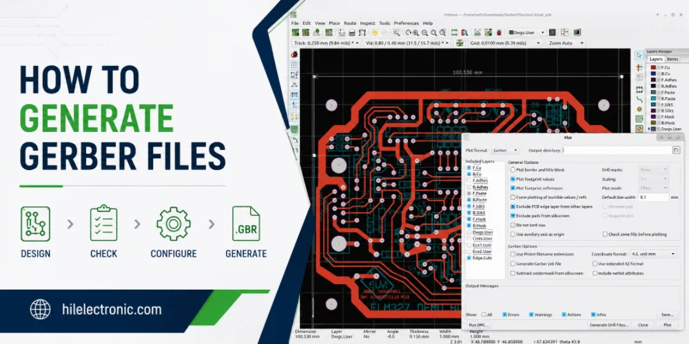
How to Generate Gerber Files for PCB Manufacturing
Figure 1. how to generate Gerber files image for Highleap...
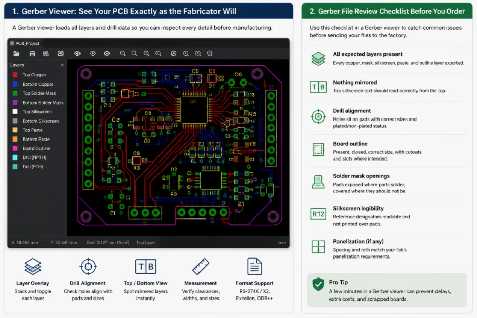
Gerber File Review Checklist: How to Check PCB Files Before You Order
Figure 1. Gerber file review catches missing layers, drill...
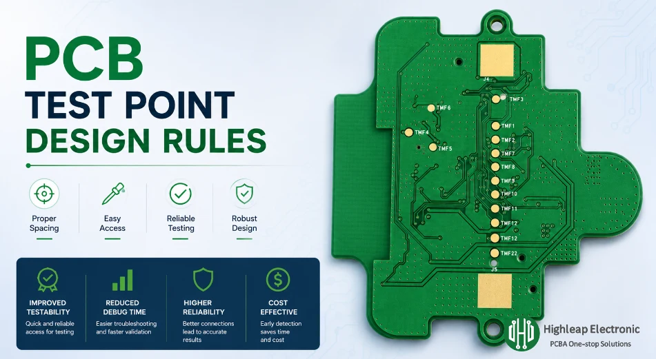
PCB Test Point Design Rules for Debug and ICT
Figure 1. PCB test point design rules help make debugging,...

PCB Jumper Wire: Uses, Types, and Design Tips
Figure 1. PCB jumper wires are useful for prototypes and...
How to get a quote for PCBs
Let us run DFM/DFA analysis for you and get back to you with a report.
You can upload your files securely through our website.
We require the following information in order to give you a quote:
-
- Gerber, ODB++, or .pcb, spec.
- BOM list if you require assembly
- Quantity
- Turn time
In addition to PCB manufacturing, we offer a comprehensive range of electronic services, including PCB design, PCBA (Printed Circuit Board Assembly), and turnkey solutions. Whether you need help with prototyping, design verification, component sourcing, or mass production, we provide end-to-end support to ensure your project’s success. For PCBA services, please provide your BOM (Bill of Materials) and any specific assembly instructions. We also offer DFM/DFA analysis to optimize your designs for manufacturability and assembly, ensuring a smooth production process.