
Back to blog
An In-Depth Overview of Keyboard PCB Technology

Introduction
PCBs are integral components in all electronic keyboard devices, from computer keyboards to musical instruments. They provide the foundation for mounting and interconnecting the various switches, sensors, controllers and other components that make up the keyboard system. The PCB translates the user’s key presses into corresponding input signals to the connected device.
This article provides a comprehensive overview of the various aspects of keyboard PCB technology. It covers the different types of keyboard PCBs, critical design considerations, manufacturing approaches, material choices and components involved in building reliable and functional keyboard PCBs tailored for specific applications. The aim is to equip design engineers with in-depth knowledge to effectively incorporate keyboard PCB technology into electronic products.
What is a Keyboard PCB?
A keyboard PCB refers to the printed circuit board assembly that serves as the foundation of an electronic keyboard device. The PCB houses and interconnects all the switches, sensors, microcontrollers, connectors and other active/passive components that make up the keyboard system.
When a user presses a key on the keyboard, it actuates the corresponding switch mounted on the PCB below. This switch closure is detected by the keyboard’s control electronics and converted into appropriate input signals which are communicated to the connected host system that the keyboard is interfaced with.
Keyboard PCBs are fabricated in a wide variety of sizes and layouts depending on the type of keyboard application and form factors required. Full-size computer keyboard PCBs accommodate over 100 keys while compact mobile keyboard PCBs may have less than 40 keys in smaller footprints.
Keyboard PCB Paramenters


Types of Keyboard PCBs
There are several types of keyboard PCBs tailored for different applications:
Mechanical Keyboard PCB – Used in mechanical keyboards which use individual physical switches for each key rather than rubber dome membranes. This allows custom switch types to be used for enhanced tactile feedback.
Gaming Keyboard PCB – Optimized for gaming with features like programmable RGB backlighting zones, macro keys and anti-ghosting switch matrices.
Laptop Keyboard PCB – Compact, thin and designed to be integrated within tight notebook and laptop enclosures.
Ergonomic Keyboard PCB – Ergonomically sculpted layouts to enable natural wrist positioning and typing motion to reduce fatigue.
Flexible Keyboard PCB – Manufactured on thin, flexible substrates which allow the keyboard to be rolled/bent making them ideal for portable applications.
Wireless Keyboard PCB – Incorporate wireless connectivity such as Bluetooth to connect with host devices without physical cables.
Numeric Keypad PCB – Only consist of the numeric keypad section for financial/POS applications requiring numeric data entry.
Multimedia Keyboard PCB – Have dedicated keys for controlling multimedia applications, such as play/pause, volume control etc.
The choice depends on form factor, functionality, interface and usage environment needs.
Design Considerations for Keyboard PCBs
Several key factors have to be considered when designing an optimal keyboard PCB:
- Size and Layout – The keyboard size and key layout must match ergonomic, form factor and application requirements.
- Switch Type – The right mechanical switch type providing the desired tactile feedback, force profile and audible click must be chosen.
- Switch Matrix Layout – Optimal switch matrix routing minimizing ghosting while reducing wiring complexity.
- Interface – Selection of hardwired (PS/2, USB) or wireless (Bluetooth, RF) keyboard interface technology.
- Backlighting – Inclusion of per-key RGB LED backlighting for illumination and aesthetics.
- Onboard Controllers – Microcontroller capabilities for managing keyboard state, backlighting, macros etc.
- EMI Shielding – Inclusion of grounded shielding enclosures and gaskets for reducing electromagnetic interference.
- Customization – Support for switch hot-swapping, alternate keycaps and user programmability.
Careful consideration of these parameters results in a keyboard PCB optimally tailored for its intended application and usage requirements.
Mechanical Switches Used in Keyboard PCBs

Mechanical keyboards use individual physical switches under each keycap as opposed to rubber dome membranes in cheaper keyboards. These switches come in various types providing different tactile responses and audible signatures. Common mechanical switches consist of:
- Spring – Returns the key to resting position after being pressed. The spring force determines the resistance or actuation force of the key.
- Stem – Moving component attached to the keycap that slides up/down to make and break electrical contact.
- Leaf spring – Makes moving contact with the stem to complete the electrical switching circuit.
- Housing – Holds the switch components together and provides mechanical stability.
- Contacts – The fixed pads on the PCB that the moving contacts connect to when the switch closes.
Varying the internal components of the mechanical switch allows creating different force profiles from light and linear to heavy and clicky actuation.
Mechanical Switch Types for Keyboard PCBs
Keyboard PCBs can accommodate various types of mechanical key switches. The main categories are:
Linear Switches – Smooth linear travel without any tactile bump or click feedback at actuation point. Popular options include Cherry MX Red, Black, Silver, Nature White etc.
Tactile Switches – Provide a tactile bump but no audible click or noise at the actuation point. Example switches are Cherry MX Brown, Clear, Grey, Nature White.
Clicky Switches – Exhibit both a tactile bump as well as a distinctive audible click at actuation. Common clicky switches are Cherry MX Blue, Green, Nature White, Kailh Box White.
Silent Switches – Designed to generate minimal noise even on full depression after actuation. Useful in open office environments. Cherry MX Silent Red/Black are popular silent linear switches.
Different users prefer certain key switch types based on the desired feel, sound and typing experience. Keyboard PCBs can be designed to work with a wide variety of available specialty mechanical switches.
Mechanical Switch Mounting Styles Used in Keyboard PCBs
Mechanical switches come in two orientation styles – 3 pin and 5 pin – that dictate how they interface with the PCB:
3 Pin Switches – Have two pins for the electrical contacts and one for mounting. Require additional plate support or thicker PCBs for stability.
5 Pin Switches – Feature two additional plastic guide pins for alignment and stability when soldered directly to the PCB without a plate.
For plate-mounted keyboards, either type works since the plate provides mechanical support. Hot-swappable PCBs typically only work with 3 pin switches.
The extra pins can be clipped off if a 5 pin switch is used in a 3 pin keyboard PCB application. The orientation does not affect switch electrical or tactile characteristics.
Role of Plates in Keyboard PCBs
Plates are metal (aluminum, steel) or plastic (polycarbonate, acrylic) sheets that mount above the PCB and below the switches:
- They have cutouts that each key switch protrudes through while being secured to the plate.
- Plates provide structural rigidity and resistance against switch deformation under intense pressing.
- They ensure switch alignment and spacing consistency across the keyboard.
- Plates reduce keyboard flex and improve typing feel.
Plates are mandatory for mechanical integrity in plate-mounted switch keyboards. Some PCB-mounted keyboards can optionally omit plates to reduce cost and thickness.
Building a Custom Keyboard PCB

Electronics enthusiasts can design and construct their own custom keyboard PCBs:
Schematic Design – Create the keyboard circuit schematic with components like microcontroller, switches, LEDs etc.
PCB Layout – Design the physical PCB with the components laid out and switch matrix defined.
Firmware Code – Write firmware logic and lighting control code for the microcontroller.
3D Modeling – Model the keyboard enclosure and plate in CAD software.
PCB Fabrication – Get the designed PCB manufactured and components sourced.
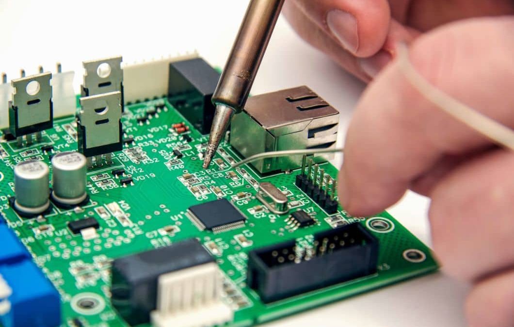
Assembly – Solder components like switches, controller, connectors on the fabricated PCB.
Flashing Firmware – Program the control firmware onto the microcontroller.
Testing – Validate keyboard functionality before final integration.
Enclosure Integration – Assemble the keyboard in the 3D printed or factory manufactured enclosure.
Building a custom keyboard is greatly rewarding but requires significant design, coding and fabrication skills along with access to the necessary component sources and manufacturing services.
Components Used in Keyboard PCBs
The key components that make up a functional keyboard PCB circuit include:
Power Supply – Keyboards use +5V or +3.3V power provided over their host interface (USB/wireless). Onboard voltage regulation may also be incorporated.
Microcontroller – This processes key presses, runs lighting effects, handles wired/wireless communication etc. Example MCUs are Atmega32, RP2040, Elite-C.
Switches – Discrete mechanical key switches or rubber dome switch matrices used for user input.
Switch Diodes – Used to prevent electrical switch matrix ghosting issues allowing more simultaneous key presses.
Key LEDs – Incorporate single color or RGB LEDs under each key for illumination and effects.
Pull-up Resistors – Used for reliable switching and to prevent false actuations.
ESD Protection – Protects sensitive control electronics from electrostatic discharges.
Filtering Capacitors – Reduces electrical noise interference on keyboard data lines.
Communication Interface – Wired interfaces like USB or wireless like Bluetooth for host connectivity.
Comparing Standard vs Mechanical Keyboard PCBs

There are some notable differences between basic membrane-based keyboard PCBs versus mechanical keyboard PCBs:
- Switching Mechanism – Membrane keyboards use printed circuits on a flexible membrane that flex when pressed. Mechanical keyboards have individual separate switches for every key.
- Tactile Feedback – Membrane keyboards have minimal tactile feedback with a soft mushy feel. Mechanical switches provide precise tactile and audible feedback with a crisp press.
- Switch Customization – Mechanical keyboards allow using different specialized switch types per user preference. Membrane keyboards offer minimal customization or switch choices.
- Lifespan – Individual mechanical switches are rated for 50+ million keystrokes. Membrane keyboards wear out after 5-10 million presses leading to failures.
- Signal Processing – Membrane keyboards use a passive capacitive sensing matrix. Mechanical keyboards employ active digital switching requiring diodes.
- Cost – Mechanical keyboard PCBs with discrete switches cost many times more than membrane keyboard PCB assemblies.
Overall mechanical keyboards offer superior longevity, customization and user experience over membrane based designs.
Common Keyboard PCB Sizes
Keyboard PCBs come in varying sizes depending on the number of included keys. Some common sizes are:
- 40% – Ultra compact format with alpha keys and some punctuation. Requires Fn key combinations.
- 60% – Includes alpha keys, modifiers, arrows but lacks function and nav keys. Popular “poker” size.
- 65% – Similar to 60% with added dedicated arrow keys. Used in some laptops.
- 75% – Contains alpha keys, modifiers and function keys but no numpad.
- 80%/TKL – Tenkeyless with no numpad but all other keys present.
- 100% – Full-size board with integrated numpad and all keys. Most common PC format.
Smaller keyboard PCB sizes are used to maximize portability while larger ones optimize productivity. The application context guides size selection.
Designing the Keyboard PCB Layout

The PCB layout arranges the components and routes their connectivity to implement the keyboard circuit in the real physical constraints:
- POSITION COMPONENTS – Microcontroller, connectors, switches grouped functionally and spaced appropriately.
- MATRIX ROUTING – Optimized switch matrix connecting rows/columns detects key presses reliably.
- CONTROL CIRCUITRY – Minimal length high-speed routings for the MCU.
- ISOLATION – Keep noisy digital traces away from analog sensitive ones.
- FORM FACTOR – Component positions match external enclosure constraints of the keyboard.
- SERVICEABILITY – Test points provided to validate functionality.
- FABRICATION – High yield board house manufacturing processes considered.
Well-planned keyboard PCB layouts minimize complexity and crosstalk while being easy to manufacture and assemble in volume.
PCB Copper Thickness Selection for Keyboards
The PCB copper thickness depends on the required current carrying capacity:
- Standard keyboard traces carry only low current signal levels, so 1 oz. copper (35 μm) is typical.
- Some specialty RGB-backlit gaming keyboards use heavier 2 oz. copper (70 μm) to handle higher LED currents without voltage drops.
- Maximum allowable PCB trace width and clearance also factor into copper weight selection.
In most cases, 1 oz. copper offers the right balance of conductivity versus manufacturability for keyboard PCBs given their low power requirements.
Switch Mounting Styles in Keyboard PCBs

Mechanical keyboard switches are physically mounted onto the PCB using either solder joints or hot-swap sockets:
Soldered – The switch terminals are soldered directly to the PCB pads to both electrically connect and mechanically anchor the switch. Provides reliable permanence but isn’t removable.
Hot-Swap Socket – A socket pin header is pre-soldered to the PCB and the switch pins plug into this socket without any soldering needed. Allows switch swapping but sockets can wear out over repeated insertion cycles.
Hot-swap keyboards require a plate to reinforce switch mounting while soldered keyboards can optionally omit the plate if thickness is a constraint. The desired customization flexibility guides the choice between soldered and hot-swap keyboard PCB constructions.
Keyboard PCB Plate Material Selection
The plates mounted to keyboard PCBs are typically constructed using:
Aluminum – Most common keyboard plate material.Provides rigidity at low weight. CNC machined to high accuracy. Can be anodized in different colors. Minimal cost.
Stainless Steel – Offers greatest mechanical stiffness but is heavier. Low corrosion and some aesthetic customization like paint fills.
Brass Plate – Brass plates are known for their softer bottom-out feel, providing a subtle cushioning effect. They produce a lower-pitched sound compared to aluminum plates and are often chosen for sound dampening purposes. Brass plates may add weight to the keyboard due to their density.
Carbon Fiber – Very lightweight and rigid option. Visually attractive with woven finish. Costs significantly more than aluminum.
Acrylic – Low cost plastic option. Allows edge light guides when paired with underglow LEDs. Higher flexibility than metal plates.
FR4 Plate – FR4 plates are frequently chosen for budget keyboards due to their affordability. They offer a distinct sound profile with a deeper tone compared to aluminum plates. However, it’s worth noting that FR4 plates have the tendency to dampen the overall sound of a keyboard, potentially reducing its vibrancy.
Acrylic Plate – Acrylic plates are not commonly recommended unless they are of sufficient thickness. Thin acrylic plates carry a risk of cracking or shattering. Thicker acrylic plates can produce a deeper sound profile similar to other plastic plates.
Polycarbonate – Another plastic alternative with good durability and transparency for lighting effects. Provides moderate tactile feedback.
The desired structural rigidity, weight, durability, cost and cosmetic preferences guide the plate material selection when designing a keyboard PCB.
Kayboard PCB production process

Testing of keyboard pcb

Package of keyboard pcb

Conclusion
Keyboard PCBs encompass a diverse range of technologies tailored for the expansive application space spanning consumer, industrial and niche domains. This article provides a holistic overview of the varied considerations involved in engineering optimized keyboard PCB systems based on contextual requirements.
By comprehending the interdependent relationships between keyboard PCB materials, mechanical switch selections, layout and routing factors, microcontroller capabilities, interface options and usage environments; design engineers can make prudent choices to create customizable, high performance and reliable keyboard implementations.

Recommended Posts
What is a Cold Joint Solder and How Can You Prevent it?
[pac_divi_table_of_contents title="On this article"...
Demystifying BGA Soldering: Tips and Best Practices
[pac_divi_table_of_contents title="On this article"...

Selecting the Right PTFE Material for Your PCB
[pac_divi_table_of_contents title="On this article"...

20 Analog Circuits Engineers Should Master
[pac_divi_table_of_contents title="On this article"...