
Custom Radar PCB Design, Manufacturing and Assembly Services

In an era of rapid technological advancement, radar systems are fundamental to industries ranging from automotive and aerospace to telecommunications and defense. These systems rely on a critical component: the Radar PCB. A well-designed Radar PCB ensures accurate signal processing, robust performance, and reliable operation under demanding conditions. This article explores the fundamentals of Radar PCBs, their components, materials, applications, and design considerations to help you make informed decisions for your projects.
What Is a Radar PCB?
A Radar PCB is a specialized circuit board designed to generate, transmit, and receive high-frequency radar signals. It serves as the core component in radar systems, supporting essential elements such as the antenna, RF circuitry, and signal analysis components. Radar PCBs are integral to the operation of radar systems, which rely on the precise management of high-frequency signals. These PCBs work by generating radar signals through an RF circuit, transmitting them via an antenna, and receiving the reflected signals (echoes) after they hit an object. These echoes are then processed to determine key information, such as the object’s location, velocity, or environmental conditions.
There are various types of Radar PCBs, including RF PCBs, microwave PCBs, and millimeter-wave PCBs. These are designed to handle specific frequency ranges and performance requirements:
-
- RF PCBs are used for lower microwave frequencies (up to around 10 GHz) and are typically deployed in automotive radar systems or weather radar.
- Microwave PCBs work in the range of 1 GHz to 30 GHz, often used for medium- to long-range radar systems in aerospace and defense applications.
- Millimeter-Wave PCBs operate at frequencies above 30 GHz and are critical for advanced radar systems, such as those used in autonomous vehicles, industrial sensing, and 5G communications.
This ability to handle high-frequency signals efficiently makes Radar PCBs indispensable for applications that require precise detection and real-time data processing. From automotive safety systems and aerospace navigation to defense and weather monitoring, Radar PCBs are crucial for enabling reliable, high-performance radar systems. Their design ensures that radar systems can operate with accuracy and efficiency, even in the most demanding environments, making Radar PCBs a foundational technology in industries where real-time decision-making is critical.
Core Components of a Radar PCB
A Radar PCB is a critical component in radar systems, enabling the precise transmission, reception, and processing of signals. It achieves this functionality through the integration of several essential components:
-
- Transmitter: Amplifies the radar signal generated by waveform generators to high-power levels, ensuring the signal can travel long distances.
- Receiver: Processes reflected signals (echoes) by amplifying, filtering, and demodulating them to extract meaningful data, such as distance, velocity, and object detection.
- Antenna: Sends the radar signal into the environment and receives reflected echoes. Key types include parabolic reflectors, phased arrays (electronically steerable), and planar arrays for compact systems.
- Duplexer: Acts as a switch, allowing the antenna to alternate between transmission and reception modes without damaging the sensitive receiver.
- Waveguides: Transmission lines that carry high-frequency signals between the transmitter, antenna, and receiver with minimal loss.
- Threshold Decision Circuit: Compares the processed signal strength against a predefined threshold to determine whether a valid target is present or if the signal is just noise.
These components form the foundation of a Radar PCB, working together to ensure seamless signal flow, accuracy, and reliability in radar applications. The integration of these components enables radar systems to perform critical tasks such as object detection, range measurement, and velocity calculation. Whether used in automotive safety systems, military tracking, or aerospace navigation, a well-designed Radar PCB ensures high performance and operational precision.
Key Features of Radar PCBs
Radar PCBs are critical for enabling high-frequency radar systems to function reliably and efficiently. These specialized circuit boards are designed to meet demanding performance requirements, such as handling microwave and millimeter-wave frequencies, ensuring thermal stability, and operating in harsh conditions. Below is a professional and detailed overview of the key features that define a high-performance Radar PCB.
1. High-Frequency Operation
Radar systems operate at frequencies ranging from microwave bands (e.g., 24 GHz) to millimeter-wave bands (e.g., 77 GHz and beyond). Such high frequencies are essential for applications like automotive collision detection, weather radar, and defense systems. To maintain signal strength and clarity, Radar PCBs must minimize signal loss and electromagnetic interference (EMI). This is achieved through the use of specialized low-loss materials like Rogers RO4003, PTFE-based laminates, and other high-frequency substrates. Additionally, shorter and more direct signal pathways are incorporated into the design to reduce insertion loss and ensure signal integrity.
2. Controlled Impedance
Impedance control is essential for RF and microwave radar circuits to ensure smooth signal propagation across the PCB. Without precise impedance matching, radar signals can suffer from reflection, loss, and distortion, degrading system performance. Radar PCBs achieve controlled impedance through:
-
- Optimized trace dimensions (width, thickness, spacing) based on the substrate’s dielectric constant (Dk).
- Careful stack-up design to manage impedance within multi-layer boards by using ground planes and shielding.
- Simulation tools, such as HFSS or CST Microwave Studio, to predict and validate impedance behavior before fabrication.
Accurate impedance control is critical in applications such as automotive radar sensors and defense systems, where signal reliability directly impacts safety and functionality.
3. Thermal Management
Radar systems, particularly high-power radar transmitters, generate significant heat during operation. Without proper thermal management, excessive heat can degrade components, shorten lifespan, and compromise performance. Radar PCBs employ several thermal control techniques, including:
-
- Thermal vias: Conduct heat away from surface-mounted components to internal or external heat dissipation layers.
- Metal-core PCBs (MCPCBs): Aluminum or copper cores improve thermal conductivity for heat-intensive applications.
- High thermal-conductivity substrates, such as ceramic-filled PTFE, effectively transfer heat away from high-power areas.
- Heat sinks and spreaders: Provide external cooling solutions for power amplifiers and RF components.
Effective thermal management ensures stable performance and reliability, especially in continuous, high-load applications like air traffic control radar and industrial sensing systems.
4. Durability in Harsh Environments
Radar PCBs are frequently deployed in environments characterized by extreme temperatures, humidity, vibration, and chemical exposure. For applications such as aerospace, military radar, and automotive systems, durability is paramount. To ensure long-term reliability, radar PCBs are designed with:
-
- High-temperature stability: Materials with high Glass Transition Temperature (Tg) prevent warping or degradation under thermal stress.
- Moisture resistance: Substrates with low moisture absorption, such as PTFE-based laminates, prevent signal loss in humid conditions.
- Mechanical reinforcement: Thicker copper layers and rigid substrates improve resistance to vibration and mechanical stress.
- Protective coatings: Conformal coatings, such as polyurethane or silicone, shield PCBs from moisture, dust, and corrosive agents.
This rugged construction allows Radar PCBs to operate reliably in critical applications like maritime radar systems, automotive ADAS, and defense tracking systems.
5. Low Dielectric Loss
Radar systems rely on the accurate transmission and reception of signals at very high frequencies. Dielectric loss, which occurs as signals propagate through the PCB substrate, can attenuate signal strength and compromise radar performance. To combat this, Radar PCBs utilize materials with:
-
- Low Dielectric Constant (Dk): Substrates like Rogers RO4350 and PTFE ensure minimal signal delay and phase distortion.
- Low Dissipation Factor (Df): A low Df reduces energy loss, preserving signal clarity and strength.
- Consistency: Uniform dielectric properties across the PCB prevent impedance mismatches and phase variation.
For millimeter-wave radar systems operating at 77 GHz or higher, low dielectric loss is especially critical to achieving long-range detection, high-resolution imaging, and fast signal processing.
6. Precision Design for High-Frequency Applications
Achieving high performance in Radar PCBs requires precision engineering and advanced design techniques. Designers must optimize the PCB layout for high-frequency RF signals while minimizing parasitic effects, noise, and losses. Key considerations include:
-
- Stack-up Optimization: Strategic layer placement for signal, power, and ground planes to enhance isolation and reduce crosstalk.
- Signal Integrity Management: Using RF shielding, ground planes, and controlled impedance traces to maintain signal clarity.
- Short Transmission Paths: Minimizing trace length and ensuring clean routing reduces phase delays and signal loss.
- Simulation and Testing: Advanced electromagnetic simulation and real-world testing validate PCB performance before deployment.
Precision in design ensures that Radar PCBs can meet the demanding performance needs of radar systems in automotive, aerospace, and industrial applications.
Radar PCBs are meticulously engineered to handle the challenges of high-frequency operation, thermal management, and harsh environments while maintaining controlled impedance and low dielectric loss. These features make them indispensable for critical applications like autonomous driving systems, air traffic control, military surveillance, and weather radar. By leveraging advanced materials, thermal solutions, and precision design techniques, Radar PCBs ensure exceptional reliability, accuracy, and performance in the most demanding conditions.
Types of Radar PCBs
Automotive and industrial radar modules can also be reviewed around Rogers RO3003 PCB manufacturing or ITEQ IT-88GMW PCB builds when the frequency plan, loss budget, and production construction are defined.
Different radar systems require specific types of Radar PCBs, each optimized for unique applications:
- Doppler Radar PCB
Uses the Doppler effect to measure the velocity of moving objects. Common in automotive radars and speed detection systems. - Monopulse Radar PCB
Measures target position by comparing signal characteristics within a single pulse. Often used for precision tracking and guidance systems. - Passive Radar PCB
Detects targets using ambient RF signals, making it ideal for applications that require minimal active emissions. - Weather Radar PCB
Analyzes precipitation and wind conditions using radio frequency signals, often combined with Doppler technology for wind speed measurement. - Pulsed Radar PCB
Emits high-intensity pulses and calculates object location based on the time delay of reflected signals. Used in applications requiring precise distance and motion detection.

Design Considerations for Radar PCBs
Designing high-performance Radar PCBs demands careful planning and attention to detail to meet the rigorous requirements of modern radar systems. Radar PCBs typically operate at microwave and millimeter-wave frequencies and are often deployed in challenging environments. To ensure reliable and efficient operation, critical factors such as signal integrity, thermal stability, and noise isolation must be carefully optimized. This article provides a comprehensive overview of the essential design aspects for achieving high-quality Radar PCBs that deliver precision, efficiency, and durability.
1. Controlled Impedance Routing
Radar PCBs operate at high frequencies, where even small impedance mismatches can lead to signal reflection, attenuation, and loss of signal integrity. Controlled impedance routing is vital to ensure that signals travel through PCB traces with minimal degradation. To achieve this, several design factors must be considered, such as trace geometry, dielectric material selection, and layer stack-up optimization. The trace width, thickness, and spacing should be precisely calculated based on the operating frequency and dielectric properties. Additionally, high-frequency simulation tools like HFSS and CST Microwave Studio are essential for validating the design. Controlled impedance routing is crucial for maintaining clean and distortion-free signals in radar systems, ensuring reliable performance across applications such as automotive radar and aerospace systems.
2. Thermal Management
Radar systems, particularly high-power applications like radar transmitters and phased array antennas, generate significant heat. Without adequate thermal management, excessive heat can cause component damage, reduce PCB lifespan, and degrade overall performance. Effective thermal management techniques include the use of thermal vias, metal core PCBs (MCPCBs), and thicker copper layers. Thermal vias help transfer heat from power-intensive components to internal layers or external heat sinks, while MCPCBs improve heat dissipation by incorporating a metal core. Additionally, using materials with high thermal conductivity, such as ceramic-filled PTFE composites, aids in effective heat management. Proper thermal management ensures long-term reliability, minimizes performance drift due to temperature fluctuations, and protects sensitive components from overheating during continuous operation.
3. Signal Loss Minimization
Signal loss, or attenuation, becomes a significant concern at microwave and millimeter-wave frequencies, where even slight imperfections can degrade radar performance. Minimizing signal loss is essential to maintain signal strength, clarity, and range. Key strategies for reducing signal loss include using short, direct routing paths for high-frequency traces, selecting low-loss dielectric materials (e.g., PTFE-based laminates), and avoiding parasitic effects such as unnecessary bends, vias, and crossovers. Smooth copper surfaces are also crucial in reducing skin effect losses, which are more pronounced at higher frequencies. By minimizing signal loss, radar systems can achieve better detection ranges, improved resolution, and higher performance in applications like weather radar and autonomous driving systems.
4. Shielding and Isolation
Radar PCBs often operate in environments with significant electromagnetic interference (EMI) that can disrupt high-frequency signals. Proper shielding and isolation are necessary to ensure signal integrity and prevent degradation from noise, EMI, and crosstalk. Shielding techniques include using continuous ground planes beneath RF signal layers, adding copper shields or metal enclosures around sensitive components, and employing via fencing to contain electromagnetic fields. Additionally, isolating RF and digital circuits physically reduces the risk of interference, while differential pair routing and controlled return paths further minimize noise susceptibility. Effective shielding and isolation ensure that radar systems deliver reliable, interference-free performance, even in noisy or high-power environments.
5. Multilayer Stack-Up Optimization
Modern radar systems often require multilayer PCBs to accommodate complex circuitry, power distribution, and compact form factors. Optimizing the multilayer stack-up is essential for balancing signal integrity, isolation, and thermal management. Key considerations include strategically placing RF signal layers between ground planes to minimize EMI and crosstalk, controlling dielectric thickness for accurate impedance matching, and ensuring proper power and ground distribution to reduce noise and improve stability. Additionally, incorporating thermal management layers, such as metal cores, helps dissipate heat while maintaining mechanical stability. A well-designed multilayer stack-up enables radar PCBs to fit within compact radar modules and maintain signal integrity while minimizing electromagnetic interference.
6. Material Selection for High Frequencies
For mmWave projects, the 77 GHz radar PCB material must be selected together with the stackup, copper profile, antenna geometry, and manufacturing tolerances rather than from a laminate name alone.
Choosing the right materials for radar PCBs is essential to address challenges such as signal loss, impedance control, and thermal performance. Materials like PTFE-based laminates and Rogers high-frequency substrates (e.g., RO4350, RO3000) provide excellent dielectric stability and low dissipation factors, making them ideal for high-frequency applications. Ceramic-filled materials enhance thermal conductivity while minimizing signal loss, and low-profile copper foil reduces skin effect losses at high frequencies. The appropriate selection of materials ensures that radar PCBs meet specific frequency requirements while balancing cost, thermal performance, and durability. Material choices directly impact the overall performance, reliability, and lifespan of radar systems.
Designing a high-performance Radar PCB involves addressing a range of critical factors, including controlled impedance routing, thermal management, signal loss minimization, and shielding, while optimizing multilayer stack-ups and selecting suitable materials. By carefully managing these design aspects, engineers can achieve superior signal integrity, minimal interference, and consistent performance. This ensures that radar systems operate reliably across demanding applications, such as automotive ADAS, aerospace navigation, weather monitoring, and defense radar. A well-designed Radar PCB is the foundation for advancing the next generation of precision radar technologies, providing the reliability and performance required for today’s cutting-edge radar systems.
Conclusion
Radar PCBs are the backbone of modern radar systems, enabling precise detection, real-time processing, and reliable communication across a range of industries. Their ability to handle high-frequency signals with minimal loss, combined with durability and advanced thermal management, makes them critical for applications like automotive safety, aerospace navigation, and industrial automation.
When designing and manufacturing a Radar PCB, partnering with an experienced and trusted PCB manufacturer ensures optimized performance, material selection, and quality assurance. Investing in high-quality Radar PCBs guarantees the reliability and accuracy needed for next-generation radar systems, empowering industries to operate smarter, safer, and more efficiently.
Get a Free PCB & PCBA Quote

Recommended Posts
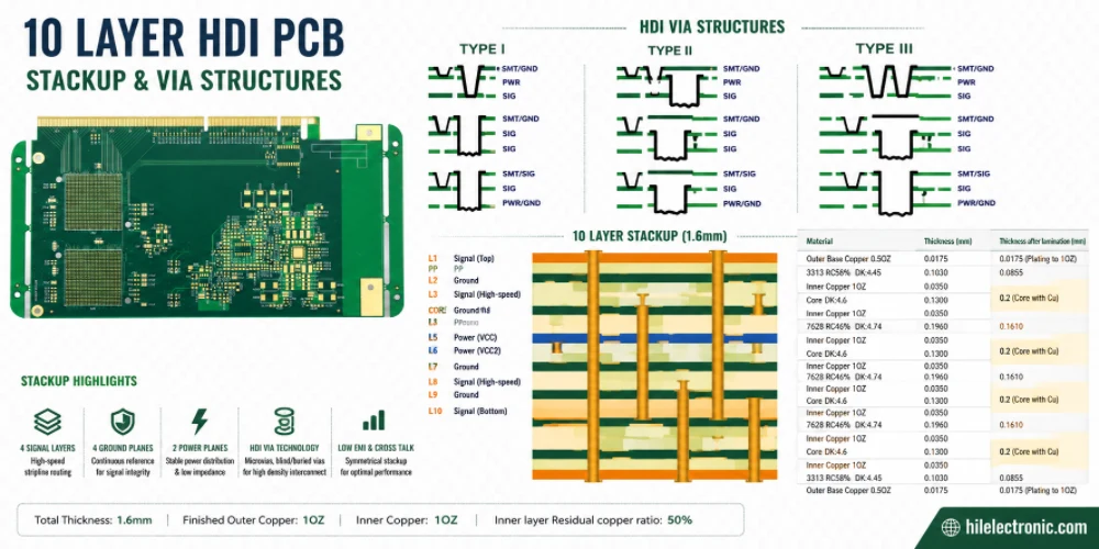
10 Layer HDI PCB Engineering for Microvias and BGA Escape
Figure 1. 10 layer HDI PCB engineering for microvias and...

8 Steps to Manufacture a Perfect Aluminum PCB
Figure 1. Aluminum Pcb manufacturing reference for PCB...

Outdoor Lighting PCB Manufacturing & Assembly by Highleap Electronics
Figure 1. outdoor lighting PCB production and assembly...

Lighting PCB Manufacturer: PCB Fabrication, PCB Assembly & Turnkey LED Lighting
Figure 1. Lighting PCB manufacturer overview for LED light...
How to get a quote for PCBs
Let us run DFM/DFA analysis for you and get back to you with a report.
You can upload your files securely through our website.
We require the following information in order to give you a quote:
-
- Gerber, ODB++, or .pcb, spec.
- BOM list if you require assembly
- Quantity
- Turn time
In addition to PCB manufacturing, we offer a comprehensive range of electronic services, including PCB design, PCBA (Printed Circuit Board Assembly), and turnkey solutions. Whether you need help with prototyping, design verification, component sourcing, or mass production, we provide end-to-end support to ensure your project’s success. For PCBA services, please provide your BOM (Bill of Materials) and any specific assembly instructions. We also offer DFM/DFA analysis to optimize your designs for manufacturability and assembly, ensuring a smooth production process.