
Rigid-Flex PCB for Drone: Optimizing Compact UAV Electronics

Introduction
As drones become smaller and more powerful, engineers face increasing pressure to reduce space while maintaining electrical integrity. Rigid-flex PCBs for drones combine flexible circuits and rigid sections to enable compact interconnections for flight controllers, camera modules, and power units. This hybrid construction eliminates bulky connectors and cable harnesses that add weight and create potential failure points. UAV flexible circuits fold seamlessly within confined spaces, supporting the high-density integration required for modern drone systems.
Why Drones Need Rigid-Flex PCBs
Compact drone systems demand circuit solutions that conventional rigid boards cannot provide. Flight controllers, ESCs, cameras, and sensors must interconnect within millimeters of available space, where traditional cable assemblies consume excessive volume and add unnecessary weight. Rigid-flex PCB technology reduces connection points by integrating flexible circuits directly into the board structure.
The advantages of rigid-flex PCB for drone applications include:
- Weight reduction – Eliminating connectors and cables reduces system mass by 20-40% compared to equivalent rigid board assemblies with wire harnesses.
- Vibration resistance – Flexible circuit sections absorb mechanical stress that would fracture solder joints on cable connections, improving reliability under constant motor vibration.
- Signal integrity – Shortened trace lengths and reduced electromagnetic interference from integrated routing improve communication between flight control components.
- Space optimization – Three-dimensional folding enables compact drone system architectures impossible with rigid boards alone.
Structural Design of Rigid-Flex PCBs in UAVs
Layer Configuration
Typical UAV flexible PCB constructions use 4-layer rigid sections for component mounting combined with 2-layer flex regions for interconnection. The rigid areas provide stable platforms for processors, connectors, and power components requiring secure mechanical support. Flexible sections route between modules using polyimide film substrates that bend repeatedly without conductor fatigue.
Bending Radius and Mechanical Reliability
Flexible circuit UAV sections require minimum bend radius calculations to prevent conductor cracking during assembly and operation. Dynamic flex regions enduring constant movement need radii of at least 10 times the material thickness, while static bends formed during installation can use 6-8 times ratios. Stiffener placement at bend transitions prevents stress concentration that accelerates failure.
Material Selection
Polyimide flex boards provide the thermal stability and mechanical properties essential for UAV electronics. Standard FR-4 comprises rigid sections where dimensional stability and heat dissipation matter most. Adhesiveless constructions eliminate bond layer thickness and improve flexibility in critical bend areas. Material compatibility between rigid and flex stackups prevents delamination during thermal cycling from −40°C to 85°C typical in outdoor drone operation.

Rigid-Flex PCB for Drone
Key Applications in Compact Drone Systems
Flight Controller Integration
Flight controller rigid-flex PCB designs consolidate processor boards with sensor interfaces through flexible interconnects. IMU, GPS, and barometer modules connect via flex tails that route through airframe mounting points without connectors. This integration reduces assembly time and eliminates wire harness mapping errors during production.
Camera Module Connection
Gimbal systems require flexible connections that endure continuous rotation while maintaining signal integrity for video transmission. Rigid-flex constructions place camera interface circuitry on rigid sections while flexible regions follow gimbal movement through full range of motion. This approach eliminates the wire fatigue issues common in ribbon cable implementations, extending service life beyond 100,000 movement cycles.
Battery and Power Distribution
Power distribution boards benefit from rigid-flex PCB for drone power systems by combining high-current rigid layers for battery connections with flexible branches routing to individual ESCs. Rigid sections provide thermal mass for current-handling traces and mounting surfaces for power connectors. Flexible portions reduce mechanical stress on solder joints from vibration.
Gimbal Control Integration
Gimbal control units require precise motor drive signals delivered through flexing connections. UAV PCB assembly using rigid-flex technology maintains controlled impedance through bend regions, preserving signal quality for brushless motor commutation. The mechanical compliance of flexible sections prevents vibration feedback from gimbal movement affecting flight controller mounting.
Design and Manufacturing Considerations for Rigid-Flex PCB
Stack-up Optimization
Rigid-flex PCB design requires careful planning of layer transitions between rigid and flexible zones. Copper weight selection balances flexibility needs against current-carrying capacity, typically using 0.5 oz copper in dynamic flex regions and 1-2 oz in rigid sections. Via placement avoids flex areas where barrel stress causes cracking, instead concentrating interconnects within rigid zones.
Controlled Impedance in Bending Regions
High-speed signals crossing flexible circuit UAV sections require impedance control through bend radius changes. Trace width and spacing calculations must account for dielectric thickness variations as polyimide compresses during flexing. Differential pair routing maintains tight coupling through transitions to preserve signal integrity for USB, MIPI camera interfaces, and SPI sensor connections.
Via Protection and Reliability Testing
Manufacturing requirements for UAV flexible PCB include:
- Coverlay protection – Protects copper traces in flex regions while flexible solder mask provides abrasion resistance in lower-stress areas.
- Via reinforcement – Teardrop pad geometry at rigid-flex boundaries distributes mechanical stress and prevents annular ring separation.
- IPC-6013 compliance – Class 3 specifications ensure manufacturing processes meet aerospace reliability standards.
- Flex cycle testing – Verification includes 100,000+ bend cycles and thermal shock qualification from −55°C to 125°C.
Advantages and Trade-offs of Rigid-Flex PCB for Drone Systems
Performance Benefits
The lightweight drone PCB benefits of rigid-flex construction directly improve flight performance through reduced system mass. Eliminating connectors removes 15-30 grams from typical consumer drones, extending flight time by 2-3 minutes. Space-saving rigid-flex PCB designs enable smaller airframes or increased battery capacity within existing envelopes.
Design and Cost Considerations
Manufacturing complexity increases costs 40-60% over equivalent rigid board assemblies with cable harnesses. Design iterations require specialized tooling and longer lead times compared to conventional PCB processes. Engineering teams must coordinate mechanical and electrical design requirements simultaneously, demanding cross-discipline collaboration early in development.
Conclusion
Rigid-flex PCB technology addresses the fundamental challenges of compact drone electronics through integrated flexible circuits, connector elimination, and vibration-resistant construction. The three-dimensional routing capability enables system architectures that optimize both volume and weight while maintaining signal integrity under demanding flight conditions. Design complexity and manufacturing costs represent significant considerations, yet the performance improvements justify adoption for production programs where space utilization and reliability determine system success.

Recommended Posts
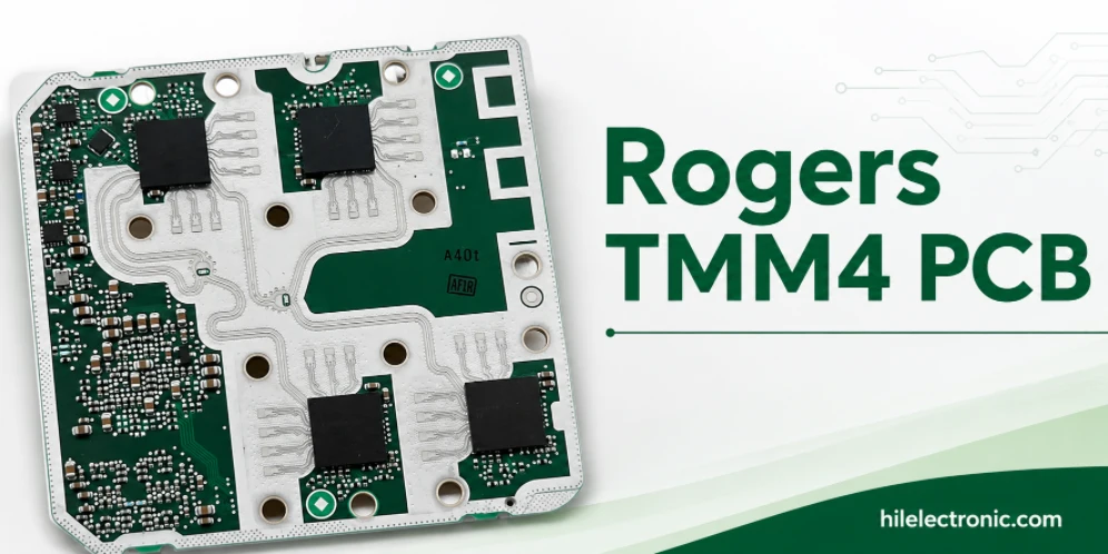
Rogers TMM4 PCB Manufacturer for Compact Microwave Filters
TMM4 is most useful when a microwave circuit must become...
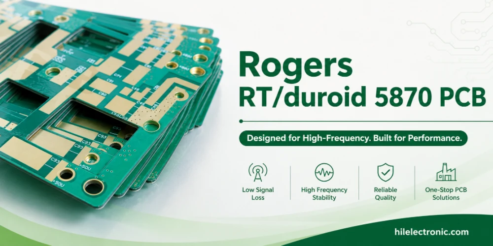
RT/duroid 5870 PCB Manufacturer for Low-Loss PTFE RF Circuits
RT/duroid 5870 is chosen when the RF path needs low loss,...
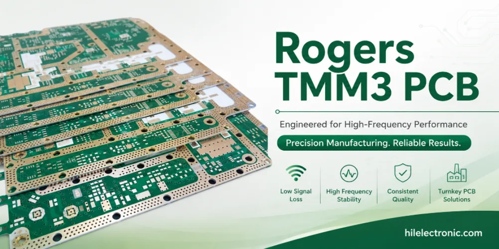
Rogers TMM3 PCB Manufacturer for Mechanical RF Modules
TMM3 is selected when an RF circuit must behave as part of...

Rogers RO3003 PCB Manufacturer for Automotive Radar and mmWave Modules
A 77 GHz radar board is purchased as a working sensor...
How to get a quote for PCBs
Let‘s run DFM/DFA analysis for you and get back to you with a report. You can upload your files securely through our website. We require the following information in order to give you a quote:
-
- Gerber, ODB++, or .pcb, spec.
- BOM list if you require assembly
- Quantity
- Turn time
In addition to PCB manufacturing, we offer a comprehensive range of electronic services, including PCB design, PCBA, and turnkey solutions. Whether you need help with prototyping, design verification, component sourcing, or mass production, we provide end-to-end support to ensure your project’s success.
For PCBA services, please provide your BOM (Bill of Materials) and any specific assembly instructions. We also offer DFM/DFA analysis to optimize your designs for manufacturability and assembly, ensuring a smooth production process.