
TMM Temperature Stable PCB Manufacturing
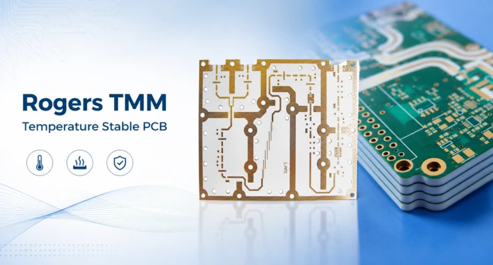
Table of Contents
- Rogers TMM Temperature Stable PCB Overview
- Rogers TMM Material Family and Grade Selection
- Dk Drift, TCDk and RF Circuit Stability
- CTE Matching and Plated-Through-Hole Reliability
- Thermal Design for Temperature-Stable TMM PCB
- Fabrication Controls for Rogers TMM PCB Manufacturing
- Thermal Qualification and Board Use
- Qualification, Testing and Documentation
- Rogers TMM Temperature Stable PCB RFQ Checklist
- Rogers TMM Temperature Stable PCB FAQ
A temperature-stable TMM PCB should be evaluated by how the finished RF structure behaves across the required temperature range. Dk change, thermal expansion and plated-hole reliability can all matter, and the relevant limits depend on the exact grade and program profile. A Rogers TMM temperature stable PCB is used when a high-frequency circuit must keep predictable electrical behavior and mechanical reliability across hot, cold and cycling environments. In RF and microwave products, temperature stability is not a secondary material feature. It affects impedance, phase length, resonant frequency, plated-through-hole reliability, assembly yield and long-term field performance.
Rogers TMM laminates are ceramic-filled thermoset microwave materials designed for high-reliability stripline and microstrip applications. The family combines a wide range of dielectric constants, low thermal coefficient of dielectric constant, copper-matched coefficient of thermal expansion and good dimensional behavior during PCB fabrication. This can make TMM a practical option for radar modules, antenna systems, satellite communication electronics, aerospace RF hardware, microwave filters and power-amplifier boards when the required thermal behavior exceeds what the selected FR-4 or other RF laminate can provide.
This guide rewrites the selection logic from a manufacturing and engineering perspective. Instead of treating temperature stability as a simple material label, it explains how Dk drift, TCDk, CTE, via reliability, thermal paths, fabrication controls and qualification data should be translated into a real PCB specification.
This page addresses temperature-stable TMM construction through Dk behavior, thermal expansion matching and reliability of the finished PCB. The manufacturing discussion centers on stackup, material pairing, plated structures and the qualification conditions defined for the product.
Rogers TMM Temperature Stable PCB Overview
The purpose of using Rogers TMM is not only to build a low-loss RF board. The main purpose is to reduce the combined electrical and mechanical uncertainty that appears when a high-frequency PCB operates across temperature. A good TMM PCB should keep the RF response close to the design target while also surviving drilling, plating, lead-free assembly, thermal cycling and field exposure.
Electrical stability across operating temperature
In RF design, the dielectric constant of the substrate directly affects transmission-line impedance, effective wavelength, phase delay and resonant behavior. When Dk changes with temperature, a line that was tuned at room temperature may shift at hot or cold corners. For a broadband digital board this may be acceptable; for a narrowband microwave filter, phase-matched feed network or patch antenna, the same drift can move the circuit outside its usable window.
Rogers TMM materials are selected because their thermal coefficient of dielectric constant is low compared with many general-purpose materials. This helps engineers maintain frequency response, impedance match and phase consistency over a wider temperature range. However, the drift is not zero, and each TMM grade has its own value and direction. The correct approach is to include TCDk in the tolerance budget rather than assuming that the material automatically removes all thermal drift.
Mechanical stability and plated-hole reliability
Temperature-stable PCB performance also depends on mechanical survival. A circuit can have stable Dk and still fail if the via barrels crack, pads lift or copper features are stressed during repeated heating and cooling. Rogers TMM is valued because its coefficient of thermal expansion is closely matched to copper, which supports reliable plated through holes and reduces stress between copper and dielectric layers.
This point matters especially for RF boards because vias are not only interconnects. They are often part of the RF structure: ground vias, via fences, cavity walls, thermal via arrays and plated mounting holes can all affect RF performance. If a via barrel opens or becomes intermittent, the failure may appear as unstable gain, degraded return loss, shifted filter response or complete loss of grounding.
Manufacturing stability as part of material selection
A temperature-stable Rogers TMM PCB still needs a controlled fabrication process. Material grade, laminate thickness, copper weight, drilling parameters, plating thickness, desmear quality, etching tolerance, stackup symmetry and surface finish all influence the final result. TMM materials can be processed with common PCB subtractive processes, but their ceramic-filled composition requires attention to tool wear and hole-wall quality. Highleap reviews the TMM grade, CTE relationship, board thickness and plated-hole construction against the qualification plan. Where thermal cycling is required, the profile and acceptance criteria should be fixed before production rather than added as a generic reliability claim. Exact material property values should be checked against the current supplier documentation for the specified grade and construction.
For this reason, a professional TMM PCB specification should not stop at “use Rogers TMM.” It should define the grade, dielectric thickness, finished copper, controlled impedance, hole structure, aspect ratio, thermal cycling requirements, microsection requirements and documentation level needed for the application.
Rogers TMM Material Family and Grade Selection
The Rogers TMM family includes several dielectric constant options, allowing designers to balance line width, circuit size, loss, coupling, manufacturability and thermal behavior. The grade should be selected from the complete RF requirement, not only from the headline Dk value.
| TMM grade | Process Dk @ 10 GHz | Design Dk | TCDk, ppm/°C | Typical design role |
|---|---|---|---|---|
| TMM3 | 3.27 ± 0.032 | 3.45 | +37 | Lower-Dk RF lines, antennas and circuits needing wider trace geometry. |
| TMM4 | 4.50 ± 0.045 | 4.7 | +15 | Balanced mid-Dk option for stable RF layouts and moderate miniaturization. |
| TMM6 | 6.00 ± 0.080 | 6.3 | -11 | Compact microwave circuits with very low Dk drift magnitude. |
| TMM10 | 9.20 ± 0.230 | 9.8 | -38 | High-Dk miniaturized RF circuits, filters and compact matching networks. |
| TMM10i | 9.80 ± 0.245 | 9.9 | -43 | Isotropic high-Dk design where consistent dielectric behavior is important. |
| TMM13i | 12.85 ± 0.35 | 12.2 | -70 | Maximum miniaturization and high-Dk RF structures with drift modeled carefully. |
Lower-Dk grades for wider RF geometry
TMM3 and TMM4 are useful when the design benefits from wider transmission lines, less aggressive fabrication geometry or antenna dimensions that do not need extreme miniaturization. Wider RF traces can be easier to etch consistently, and they may reduce sensitivity to small dimensional errors. These grades are often attractive when the board has enough available area and the designer wants stable high-frequency behavior without forcing very narrow conductors or tight coupling gaps.
Higher-Dk grades for compact microwave layouts
TMM10, TMM10i and TMM13i support smaller resonators, shorter line lengths and more compact RF layouts. This can be important in microwave filters, miniaturized antenna elements, couplers, matching networks and dense RF modules. The tradeoff is that high-Dk designs can become more sensitive to material tolerance, etch tolerance and temperature-dependent frequency shift. The smaller the geometry and the narrower the bandwidth, the more important it becomes to model real material data and manufacturing tolerance.
Process Dk, design Dk and purchasing accuracy
RF engineers and purchasing teams should distinguish process Dk from design Dk. Process Dk is commonly used for laminate quality control and comparison, while design Dk is intended to support circuit modeling over the relevant frequency range and structure. A quote request should specify the exact Rogers TMM grade and dielectric thickness, and the engineering documentation should identify which Dk value was used in simulation. Confusing grade names or using a generic “TMM PCB” description can result in incorrect stackup, wrong impedance and a failed RF build.
Dk Drift, TCDk and RF Circuit Stability
Dk drift is one of the most important reasons to choose a Rogers TMM temperature stable PCB. The relevant material parameter is TCDk, the thermal coefficient of dielectric constant. TCDk describes how the dielectric constant changes with temperature. The practical effect is seen in impedance, phase, wavelength and resonant frequency.
TCDk direction and circuit shift
The sign of TCDk matters. A positive TCDk means Dk rises as temperature increases, while a negative TCDk means Dk falls as temperature increases. In many resonant RF structures, a higher effective Dk tends to shorten the wavelength and can push resonance lower; a lower effective Dk can push the response in the opposite direction. This relationship is not a substitute for electromagnetic simulation, but it is useful for understanding why the same temperature profile can affect different TMM grades differently.
For example, TMM4 has a small positive TCDk, while TMM6 is slightly negative. TMM10 and TMM10i have stronger negative values, and TMM13i has the strongest negative value in the listed family. This does not mean one grade is universally better. It means the grade must be chosen according to the target Dk, circuit size, bandwidth, acceptable frequency shift and production tolerance.
Temperature-corner simulation for RF designs
Critical Rogers TMM designs should be simulated at temperature corners instead of only at room temperature. The model should include Dk tolerance, TCDk, dielectric thickness tolerance, copper thickness, surface finish, etch tolerance and component tolerance. For power RF circuits, conductor loss and device heating should also be considered because the local temperature under an active device may be higher than the ambient temperature.
A practical simulation plan normally includes nominal, hot and cold cases. For filters, the engineer should check center frequency, bandwidth, insertion loss and return loss. For antennas, the engineer should check resonance, matching, gain and pattern stability. For phased-array or timing-sensitive networks, phase length and channel-to-channel matching should be reviewed.
High-Q and narrowband sensitivity
The narrower the bandwidth, the more important Dk stability becomes. A high-Q resonator or narrow passband filter can fail with a frequency shift that would be harmless in a broadband interconnect. This is why a Rogers TMM temperature stable PCB is often specified for microwave filters, radar front ends, frequency-selective networks and antenna feed structures. The material helps reduce drift, but final stability still depends on the complete design: laminate, copper, solder mask policy, finish, enclosure loading, component placement and assembly process.
Material scope: This article addresses temperature-stable PCB fabrication when the design specifies TMM laminate. Confirm the approved grade, construction and material documentation in the RFQ.
CTE Matching and Plated-Through-Hole Reliability
Electrical stability is only half of the temperature-stable PCB requirement. The board must also withstand the specified thermal expansion and contraction. TMM thermal-expansion behavior can support plated-through-hole reliability when the stackup, drilling, plating and qualification conditions are controlled.
Copper-matched expansion in TMM laminates
When a PCB is heated, copper and dielectric materials expand. If their expansion rates are very different, stress accumulates at the copper-dielectric interface and inside plated holes. In a conventional mismatch situation, repeated thermal cycling can fatigue the copper barrel, weaken interfaces or contribute to microcracking. TMM’s copper-matched expansion behavior reduces this mismatch and supports more stable multilayer and plated-through-hole performance.
Via barrels, ground fences and thermal via arrays
RF boards often use more vias than ordinary control boards. A microwave PCB may include dense ground via fences along transmission lines, via transitions between layers, thermal vias under power devices, plated mounting holes and shield-wall structures. Each of these vias must be drilled, cleaned, plated and inspected correctly. A small via reliability issue can become an RF problem because the via is part of the electrical field structure, not only a DC connection.
For reliable Rogers TMM PCB manufacturing, designers should review via aspect ratio, annular ring, via-to-edge spacing, copper balance, via density and plating requirements before release. For thick TMM boards or high-reliability programs, representative coupons and microsections should be included so the manufacturing quality can be verified without destroying the product board.
Hybrid stackups and thermal-mechanical mismatch
Some RF products combine Rogers TMM with other materials to control cost, layer count or mechanical structure. Hybrid stackups can be effective, but they introduce additional risk because each material may have different expansion, stiffness, moisture behavior and processing limits. When TMM is combined with FR-4, bonding materials, metal backers or other high-frequency laminates, stackup symmetry and thermal-mechanical compatibility should be reviewed early. A stable TMM core cannot compensate for a poorly balanced hybrid stackup.
Thermal Design for Temperature-Stable TMM PCB
Temperature stability does not mean the PCB can ignore heat. It means the design should control both the electrical effects of temperature and the physical movement of heat through the board. Rogers TMM laminates have thermal conductivity around 0.70 to 0.76 W/m·K depending on grade, which can support heat spreading compared with many lower-conductivity microwave substrates. Still, a PCB laminate is only one part of the thermal path.
Heat flow from components to board and enclosure
For RF power amplifiers, resistive terminations, bias networks and high-current sections, the real thermal path usually includes the component package, solder joint, copper pad, thermal vias, internal copper planes, metal backer, heat sink or enclosure. A Rogers TMM PCB should be designed so heat can leave the device area efficiently. Copper pour alone is often not enough when a power device has high dissipation or when the module operates in a sealed enclosure.
Power amplifier board requirements
Power amplifier boards place combined electrical and thermal demands on the PCB. The layout needs stable matching networks, short RF grounding, controlled impedance, low-loss conductors and a strong heat path. Thermal vias should be placed in manufacturable arrays, not simply packed as tightly as possible. If via density is too high or hole quality is poor, reliability may suffer. The best design balances RF grounding, heat transfer, drill capability, plating uniformity and assembly yield.
Temperature rise and local hot spots
The operating temperature of an RF PCB is not always equal to the ambient rating in the product datasheet. A PA transistor, high-power resistor, regulator or connector solder joint can create a local hot spot. That local temperature can change nearby Dk, affect solder joints and increase mechanical stress. For critical designs, the RF simulation, thermal simulation and mechanical reliability review should use realistic local temperatures rather than a single room-temperature assumption.
Fabrication Controls for Rogers TMM PCB Manufacturing
Rogers TMM can be fabricated using common printed wiring board processes, but the process should be controlled for ceramic-filled high-frequency laminate behavior. The manufacturer should understand both RF requirements and reliability requirements, especially when the board includes tight impedance tolerance, dense vias, thick dielectric cores, metal backing or qualification coupons.
Material traceability and stackup control
The build should preserve the exact TMM grade, laminate thickness, copper foil, finished copper weight, surface finish and bonding material approved by engineering. Any material substitution can affect Dk, thickness, impedance, thermal drift and mechanical stress. For high-reliability programs, material certificates, lot traceability and retained build records are part of the product requirement, not optional paperwork.
Drilling control for ceramic-filled TMM
TMM laminates contain ceramic filler, so drilling parameters and tool condition matter. Excessive tool surface speed, low chip load or worn drill bits can increase heat, accelerate tool wear and degrade hole-wall quality. Poor hole walls can later create plating defects or reliability risks. For via-dense RF boards, drilling quality should be reviewed together with aspect ratio, minimum hole size, copper plating thickness and microsection acceptance criteria.
Routing, edge quality and dimensional accuracy
Routing and profiling also need controlled parameters because ceramic-filled laminates can wear tools faster than standard FR-4. Poor edge quality may not only be cosmetic; it can affect mechanical fit, connector seating, metal enclosure contact or RF cavity behavior. For boards that mount into machined housings or RF shields, profile tolerance, slot quality and edge plating requirements should be confirmed before fabrication.
Plating, desmear and surface finish
A reliable Rogers TMM PCB depends on clean hole walls and consistent copper plating. The process should be selected according to the board thickness, via structure, copper weight and assembly exposure. Surface finish should be chosen according to solderability, RF loss, wire bonding, shelf life and assembly method. ENIG, immersion silver, immersion tin, bare copper with OSP and other finishes can all have tradeoffs depending on frequency, bonding needs and environmental exposure.
Etching tolerance and impedance control
RF line width, copper thickness and dielectric thickness determine the final impedance and phase behavior. Temperature-stable material cannot fix poor etching control. The PCB manufacturer should confirm impedance coupon strategy, trace-width tolerance, copper thickness control and final inspection method. For filters, couplers and resonators, small variations in gap, line width or copper roughness may be more important than for ordinary transmission lines.
Thermal Qualification and Board Use
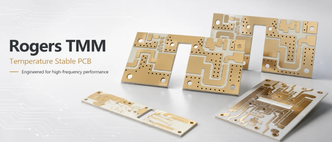
Rogers TMM is most valuable where high-frequency stability, mechanical reliability and environmental exposure overlap. The following applications commonly benefit from a temperature-stable TMM PCB specification.
Radar and phased-array RF modules
Radar systems need stable phase, predictable impedance and reliable grounding. Feed networks, couplers, dividers, filters and antenna elements may all respond to temperature. A Rogers TMM PCB can reduce Dk-related drift while supporting plated via reliability in ground fences and multilayer RF transitions. For phased-array systems, channel-to-channel consistency is often as important as absolute performance.
Satellite communication and aerospace electronics
Satcom and aerospace electronics often face wide temperature changes, vibration, reflow exposure and strict documentation requirements. Material traceability, stable Dk, low CTE mismatch and reliable plated holes all contribute to qualification confidence. TMM’s thermoset behavior and copper-matched expansion make it suitable for high-reliability RF builds where field repair is difficult or impossible. When the application has formal environmental acceptance criteria, TMM reliability requirements for aerospace boards should state the thermal profile and documentation scope before manufacture.
Outdoor antenna and communication systems
Outdoor RF equipment can experience sunlight heating, cold nights, humidity, enclosure stress and seasonal cycling. Antenna resonance, return loss and feed network phase may shift when the substrate changes temperature. A Rogers TMM temperature stable PCB helps maintain predictable behavior when paired with proper antenna design, sealing, connector control and enclosure design.
Microwave filters, couplers and resonators
Microwave filters and resonators are sensitive to Dk, copper geometry and enclosure effects. In narrowband filters, a small dimensional or dielectric change can move the center frequency. TMM reduces one major source of thermal drift, while controlled etching and RF inspection help maintain the final response. For high-Dk miniaturized filters, grade selection and fabrication tolerance should be reviewed together. For TMM4 resonator and filter boards, evaluate the required temperature corners with the actual circuit geometry rather than applying a family-wide stability assumption.
Power RF and high-thermal-load assemblies
Power RF boards need stable matching networks and reliable heat removal. TMM’s thermal conductivity and mechanical stability are useful, but the complete thermal path must be engineered through copper, vias, metal backing and enclosure contact. For production, assembly profiles and rework limits should be documented so the board does not experience uncontrolled thermal stress.
Qualification, Testing and Documentation
A temperature-stable Rogers TMM PCB should be verified according to the product risk level. A prototype for lab validation may need basic material confirmation and impedance inspection. A production board for aerospace, radar or outdoor infrastructure may need thermal stress testing, microsectioning, RF testing and complete traceability.
Thermal cycling and thermal shock planning
Thermal cycling and thermal shock are used to evaluate how the board responds to repeated expansion and contraction. The required temperature range, dwell time and number of cycles should come from the product environment or customer specification. The goal is to verify that plated holes, copper interfaces, solder joints and RF performance remain acceptable after stress.
Microsection and plated-hole inspection
Microsectioning is important for verifying drilling and plating quality. A coupon can represent critical hole sizes, aspect ratios, layer transitions and via structures. Inspection can confirm copper plating thickness, hole-wall condition, annular ring quality and signs of cracking after thermal stress. For high-reliability TMM PCB builds, before-and-after stress microsections can provide strong evidence that the fabrication process is controlled.
Impedance and RF performance at temperature
Controlled impedance should be verified with coupons, but a coupon alone may not prove that the functional RF circuit remains stable across temperature. For filters, antennas, feed networks and phase-sensitive circuits, RF testing at hot and cold corners may be needed. The acceptance criteria should define what shift is allowed, such as center frequency movement, return loss, insertion loss, gain variation or phase difference.
Documentation for repeat production
Repeatable production requires more than a first-article pass. The supplier should maintain stackup records, material lot information, process travelers, inspection reports, impedance results and any qualification data required by the customer. When a field issue occurs, this documentation helps separate design drift, fabrication defect, assembly damage and environmental overstress.
Rogers TMM Temperature Stable PCB RFQ Checklist
A clear RFQ reduces engineering delays and prevents the supplier from guessing. For a Rogers TMM temperature stable PCB, the quote package should include both electrical and reliability requirements.
Material and stackup information
- Exact Rogers TMM grade: TMM3, TMM4, TMM6, TMM10, TMM10i or TMM13i.
- Dielectric thickness, finished board thickness and layer count.
- Copper weight, copper foil requirement and finished copper thickness.
- Bonding material or hybrid stackup details if other materials are used.
- Surface finish requirement and any wire-bonding or solderability requirement.
RF and electrical requirements
- Controlled impedance values and tolerance.
- Operating frequency band and critical RF functions.
- Insertion loss, return loss, phase matching or resonance requirements if applicable.
- Impedance coupon requirements and RF test coupon requirements.
- Solder mask restrictions near RF lines, filters or antenna structures.
Mechanical and reliability requirements
- Operating temperature range and storage temperature range.
- Thermal cycling, thermal shock, solder float or reflow simulation requirements.
- Minimum hole size, via aspect ratio and plating thickness requirement.
- Microsection criteria before and after stress if required.
- Material traceability, certificate and inspection report requirements.
- Prototype, qualification or production status.
Commercial and production information
- Prototype quantity, production forecast and panelization preference.
- Target lead time and acceptable material alternatives, if any.
- Assembly exposure such as lead-free reflow, rework, connector soldering or wire bonding.
- Special packaging, shelf-life, cleanliness or export documentation requirements.
For buyers, the most important rule is simple: do not request “Rogers TMM PCB” without defining the engineering requirement behind it. Temperature stability must be translated into material grade, stackup, tolerance, inspection and qualification requirements. That is the difference between a general RF board quote and a reliable Rogers TMM temperature stable PCB build.
Rogers TMM Temperature Stable PCB FAQ
Is Rogers TMM suitable for temperature-stable RF PCBs?
TMM laminates can be suitable for RF and microwave PCBs that need stable electrical behavior and plated-through-hole reliability across temperature. The selected grade, stackup, assembly profile and qualification range must match the product requirement.
Which Rogers TMM grade has the lowest Dk drift?
Among the listed family values, TMM6 has a very low TCDk magnitude at about -11 ppm/°C, while TMM4 is also low at about +15 ppm/°C. The best grade is not determined by TCDk alone. It must also match the target Dk, line width, circuit size, bandwidth, loss requirement and manufacturability.
Does Rogers TMM eliminate thermal reliability risk?
No. Rogers TMM improves the material side of thermal reliability, but it does not eliminate process risk. Drilling quality, hole-wall preparation, copper plating, aspect ratio, stackup balance, assembly exposure and inspection still control the final reliability of the PCB.
What information is needed to quote a Rogers TMM temperature stable PCB?
The RFQ should include the exact TMM grade, dielectric thickness, stackup, copper weight, surface finish, controlled impedance, operating temperature range, via structure, reliability testing requirement, material traceability requirement and production quantity. If the circuit is a filter, antenna or phase-sensitive network, include the critical RF performance targets as well. For quotation, provide operating temperature, TMM grade, stackup, copper, reliability tests, quantity and documentation requirements. This gives engineering and quality teams a concrete basis for the manufacturing proposal.

Recommended Posts

TMM4 Filter PCB Manufacturing
TMM4 filter PCB manufacturing is controlled by the...

TMM6 PCB Fabrication
TMM6 fabrication is the process-control page for a mid-Dk...

TMM3 PCB Manufacturing for RF Modules
TMM3 PCB manufacturing is most useful where the RF module...

TMM10 PCB Manufacturing for Compact RF Designs
Table of contentsHow TMM10 Shrinks RF StructuresTMM10 vs...
How to get a quote for PCBs
Let’s run DFM/DFA analysis for you and get back to you with a report. You can upload your files securely through our website. We require the following information in order to give you a quote:
-
- Gerber, ODB++, or .pcb, spec.
- BOM list if you require assembly
- Quantity
- Turn time
For PCBA services, please provide your BOM (Bill of Materials) and any specific assembly instructions. We also offer DFM/DFA analysis to optimize your designs for manufacturability and assembly, ensuring a smooth production process.