
Back to blog
Optimizing Data Transfer and Power Delivery with USB Pinout

Circuit board with multiple USB ports
USB (Universal Serial Bus) has been a fundamental technology in electronics since its introduction in 1996. It provides a standardized interface for data transfer and power supply, making it indispensable in modern electronic devices. The USB pinout, which determines how the connector’s pins are configured to handle data and power, is crucial for the proper functioning of these devices. This comprehensive guide aims to provide electronic engineering professionals with an in-depth understanding of USB pinout configurations, data transfer protocols, and troubleshooting techniques.
Understanding USB Pinout
Types of USB Connectors
USB connectors come in various shapes and sizes, each with a specific pinout configuration tailored to different applications. The most common types include Type-A, Type-B, Mini-USB, Micro-USB, and USB-C. Each type has unique characteristics and pin configurations that influence their use in different devices.
Type-A USB Connectors
Type-A connectors are the most widely used, found on computers, chargers, and many peripheral devices. They feature four pins: two for data (D+ and D-) and two for power (VCC and GND). The power pins provide electricity to the connected device, while the data pins handle the transmission of digital information.
Type-B USB Connectors
Type-B connectors are typically used in devices such as printers and scanners. They have five pins: two for data, two for power, and one ground pin. This configuration ensures stable connections for data transfer and power delivery in more power-intensive devices.
Mini-USB and Micro-USB Connectors
Mini-USB and Micro-USB connectors are smaller versions used primarily in portable devices like cameras, smartphones, and tablets. Both types have a similar pin configuration: two power pins, two data pins, and a ground pin. Their compact size makes them ideal for devices where space is limited.
USB-C Connectors
USB-C is the latest addition to the USB family, offering a reversible connector that supports faster data transfer rates and higher power delivery. USB-C connectors have 24 pins, allowing for more versatile and powerful connections. They are designed to replace older USB types and provide a universal solution for data transfer and charging.
Importance of USB Pinout
Understanding the USB pinout is essential for ensuring proper device functionality. The pinout configuration affects data transfer speeds, power delivery, and overall device performance. Knowledge of USB pinouts is critical for troubleshooting connection issues and optimizing communication between devices.
USB Data Transfer
Data Transfer Protocols
USB data transfer involves the exchange of digital information between USB-enabled devices. The USB protocol defines the rules for data transfer, ensuring reliable and efficient communication. This protocol includes multiple layers: the physical layer, data link layer, and application layer.
Types of Data Transfers
There are several types of USB data transfers, each suited for different applications:
- Bulk Transfer: Used for large data transfers, such as file transfers between a computer and an external hard drive.
- Interrupt Transfer: Used for devices that require immediate attention, like keyboards and mice.
- Isochronous Transfer: Used for real-time data, such as audio and video streaming.
- Control Transfer: Used for device configuration and status updates.
Data Transfer Speeds
USB data transfer speeds vary depending on the version of the USB standard:
- USB 1.1: 12 Mbps
- USB 2.0: 480 Mbps
- USB 3.0: 5 Gbps
- USB 3.1: 10 Gbps
- USB 3.2: 20 Gbps
The quality of the USB cable also affects data transfer speed and reliability. High-quality cables can significantly improve performance and reduce data transmission errors.

USB Pinout
USB Power Delivery
Overview of USB-PD
USB Power Delivery (USB-PD) is a standard that enhances USB’s power delivery capabilities, allowing for faster and more efficient charging. USB-PD uses USB Type-C connectors and cables, enabling power delivery of up to 100W.
Benefits of USB-PD
USB-PD offers several advantages:
- Faster Charging: USB-PD can deliver higher power levels, allowing for faster charging of devices, including high-power devices like laptops.
- Versatile Power Delivery: USB-PD supports bi-directional power delivery, meaning devices can negotiate their power requirements to optimize charging.
- Universal Connector: The reversible USB-C connector makes it easier to connect devices and supports higher data transfer rates.
Applications of USB-PD
USB-PD is used in various applications, including:
- Charging Laptops: USB-PD can deliver enough power to charge laptops and other high-powered devices quickly.
- Powering Monitors: USB-PD can power monitors without the need for additional power cables.
- Connecting Peripherals: USB-PD can power and connect peripherals such as docking stations and external hard drives.
USB Pinout Diagrams
Understanding Pinout Diagrams
Pinout diagrams provide a visual representation of the wiring and connections within a USB cable. Each type of USB connector has a specific pinout diagram that details the arrangement and function of its pins.
Type-A USB Pinout Diagram
The Type-A USB connector has four pins:
- VBUS (Power): Supplies power to the device.
- D+ (Data): Transmits data.
- D- (Data): Transmits data.
- GND (Ground): Provides an electrical ground.
Type-B USB Pinout Diagram
The Type-B USB connector has five pins:
- VBUS (Power): Supplies power to the device.
- D+ (Data): Transmits data.
- D- (Data): Transmits data.
- GND (Ground): Provides an electrical ground.
- ID (Identification): Used to identify the connection type.
Mini-USB and Micro-USB Pinout Diagrams
Both Mini-USB and Micro-USB connectors have five pins:
- VBUS (Power): Supplies power to the device.
- D+ (Data): Transmits data.
- D- (Data): Transmits data.
- GND (Ground): Provides an electrical ground.
- ID (Identification): Used to identify the connection type.
USB-C Pinout Diagram
The USB-C connector has 24 pins, providing greater versatility:
- Power Pins: Deliver power to the device.
- Data Pins: Transmit data.
- Miscellaneous Pins: Used for additional functions such as configuration and alternate modes.

USB Pinout
Troubleshooting USB Connections
Common USB Pinout Issues
USB pinout issues can lead to various problems, including connection failures, data transfer errors, and charging inefficiencies. Common issues include damaged cables, faulty ports, incorrect device settings, insufficient power supply, and outdated drivers.
Step-by-Step Troubleshooting Guide
Step 1: Check the Cable
Inspect the USB cable for physical damage. Bent or broken pins can cause connectivity and data transfer issues. If the cable is damaged, replace it with a new one.
Step 2: Check the USB Port
Ensure the USB port is in good working condition. A damaged port can disrupt connections and data transfer. Try connecting the device to a different port to see if the issue persists.
Step 3: Check Device Settings
Verify that the device is configured correctly for USB connectivity. Incorrect settings can affect data transfer and power delivery. Consult the device manual or settings menu for guidance.
Step 4: Check the Power Supply
Ensure the power supply meets the device’s requirements. Insufficient power can cause charging issues and affect device performance. Use a power source that matches the device’s specifications.
Step 5: Update Device Drivers
Outdated drivers can cause connectivity and data transfer problems. Check for updated drivers on the device manufacturer’s website and install them if available.
Step 6: Test with a Different Device
If the issue persists, try connecting the USB device to a different computer or device. This can help determine if the problem is with the original device or the USB connection.

USB Pinout PCBA
Conclusion
The USB pinout is a vital aspect of USB technology, enabling accurate data transfer and power delivery. By understanding pinout diagrams, data transfer protocols, and troubleshooting techniques, electronic professionals can ensure optimal performance and reliability of their USB-enabled devices. This comprehensive knowledge is essential for designing, developing, and maintaining efficient electronic systems in today’s technology-driven world.
FAQ
1. How does the USB pinout configuration impact PCB design for high-speed data transfer applications?
The USB pinout configuration is critical in PCB design for high-speed data transfer as it dictates the layout and routing of the traces that carry data signals. High-speed data lines, such as those in USB 3.0 and above, require careful impedance matching and minimal crosstalk to maintain signal integrity. Designers must ensure that the differential pairs (D+ and D-) are routed symmetrically and with controlled impedance to prevent data errors and ensure reliable performance.
2. What considerations should be made when designing a PCB with multiple USB ports?
When designing a PCB with multiple USB ports, it’s essential to manage power distribution and signal integrity carefully. Each USB port should have adequate power filtering and decoupling capacitors to ensure stable power delivery. Additionally, the data lines should be routed to minimize interference and maintain proper signal integrity. Designers must also consider the thermal management of the PCB, as multiple USB ports can generate significant heat, especially when used for charging high-power devices.
3. How can PCB designers ensure compatibility with both legacy and modern USB standards?
PCB designers can ensure compatibility with both legacy and modern USB standards by incorporating versatile connectors, such as USB-C, which supports multiple USB standards through different modes. Designing the PCB to include circuitry that can detect and switch between different USB protocols (e.g., USB 2.0, USB 3.0, USB-PD) is crucial. Additionally, implementing ESD protection and appropriate power delivery circuits can help in maintaining compatibility and protecting the devices.
4. What are the key challenges in integrating USB Power Delivery (USB-PD) into a PCB design?
Integrating USB Power Delivery (USB-PD) into a PCB design involves several challenges, including managing high power levels and ensuring robust communication between devices. Designers must use high-quality components capable of handling up to 100W of power and implement efficient power management systems to prevent overheating. Furthermore, the PCB layout should minimize electromagnetic interference (EMI) and ensure reliable data communication between the USB controller and the connected devices.
5. How do advancements in USB technology, such as USB4, influence PCB design strategies?
Advancements in USB technology, such as USB4, significantly influence PCB design strategies by necessitating support for higher data transfer rates and more complex power delivery requirements. Designers must adopt advanced signal integrity practices, such as using high-speed PCB materials, controlled impedance routing, and proper grounding techniques to handle the increased data rates. Additionally, the design must accommodate the higher power demands and bi-directional power delivery capabilities of USB4, ensuring efficient thermal management and power distribution.
Sabrina has over 18 years of experience in the PCB industry, with a strong background in CAM engineering and PCB file review. She supports PCB projects from prototype to volume production, focusing on manufacturability and process reliability. Her work helps engineering teams reduce production risk and achieve stable, high-quality PCB manufacturing results.

Recommended Posts
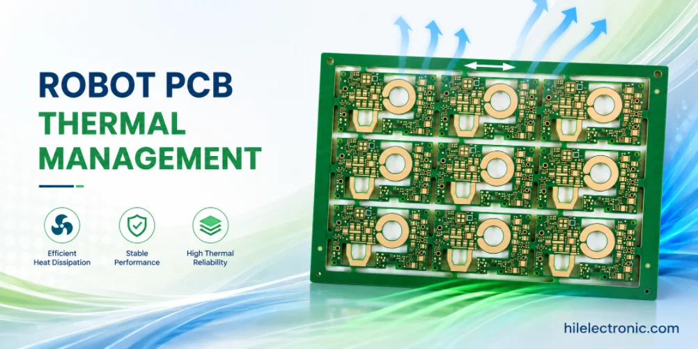
Robot PCB Thermal Management for Motors, Power Rails and Compute
Robot PCB thermal management affects service life, field...
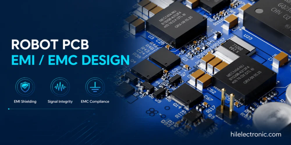
Robot PCB EMI/EMC Design for Reliable Robotics
Robot PCB EMI and EMC design affects whether a robot can...
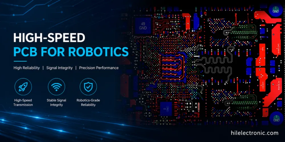
High-Speed PCB for Robotics: PCIe, DDR, MIPI and Ethernet Layout
High-speed PCB manufacturing for robotics supports data...
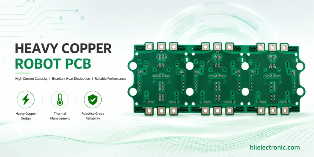
Heavy Copper Robot PCB for Motor Drives, BMS and Power Distribution
Heavy copper robot PCBs are used when standard 1 oz copper...
Take a Quick Quote