
Back to blog
The Role of PCB Stiffeners in the Electronics Industry

Table of Contents
- What PCB Stiffeners Do and Why They Matter
- Stiffener Materials: Properties, Trade-offs, and Selection Criteria
- Thickness Specifications and Dimensional Standards
- Attachment Methods: How Stiffeners Bond to Flex Circuits
- Design Rules: Placement, Tolerances, and Common Mistakes
- Application-Specific Stiffener Strategies
- Manufacturing Process: How Stiffeners Are Integrated During Production
- Specifying Stiffeners in Your Design Package
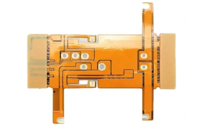
PCB stiffeners are localized reinforcement elements bonded to flexible or rigid-flex printed circuit boards to create rigid zones where the design requires mechanical stability. Without stiffeners, flex circuits would lack the planarity needed for reliable connector mating, the structural support required for SMT component placement, and the handling rigidity that automated assembly equipment demands.
Despite their importance, stiffeners are one of the most under-specified elements in flex PCB design packages — leading to assembly yield problems, connector reliability failures, and unnecessary design respins. This guide covers material selection, thickness specifications, attachment methods, design rules, and manufacturing integration in the detail that engineers need to get stiffeners right on the first build.
1) What PCB Stiffeners Do and Why They Matter
1.1 Core Functions
Stiffeners serve four distinct engineering functions on flex and rigid-flex PCBs:
- Connector support: ZIF connectors, board-to-board connectors, and card-edge interfaces require a flat, rigid mating surface. Without a stiffener backing the connector zone, the flex circuit deflects during insertion, causing intermittent contact or connector damage.
- SMT component planarity: Surface-mount components — especially fine-pitch QFPs, BGAs, and 0201/01005 passives — require a planar surface during reflow soldering. Stiffeners create a stable platform that prevents warpage and ensures coplanarity across the solder paste deposit area.
- Handling rigidity: Automated pick-and-place machines, reflow ovens, and AOI systems are designed for rigid substrates. Stiffeners give flex circuits the temporary or permanent rigidity needed to move through these machines without jams, misfeeds, or inspection errors.
- Strain relief: At the transition between a flex zone and a rigid zone (or between a flex tail and a housing connector), stiffeners distribute mechanical stress over a larger area, preventing fatigue cracking at the flex-to-rigid boundary.
1.2 Where Stiffeners Are Not the Answer
Stiffeners add thickness, weight, and cost. They should not be used as a workaround for problems that should be solved through proper stackup design or material selection. If your entire flex circuit needs to be rigid, you likely need a rigid PCB — not a flex board covered in stiffeners. If a specific zone needs moderate support but not full rigidity, a thinner polyimide stiffener or a coverlay build-up may be more appropriate than a thick FR4 panel.
2) Stiffener Materials: Properties, Trade-offs, and Selection Criteria
2.1 Material Comparison
| Material | Thermal Conductivity (W/m·K) | Density (g/cm³) | CTE (ppm/°C) | Relative Cost |
|---|---|---|---|---|
| Polyimide (PI) | 0.12–0.35 | 1.42 | 20–30 | $$ |
| FR4 | 0.25–0.30 | 1.85 | 14–17 (X/Y) | $ |
| Stainless Steel (SUS 304) | 16 | 7.93 | 17.3 | $$$ |
| Aluminum (6061-T6) | 167 | 2.70 | 23.6 | $$ |
2.2 FR4 Stiffeners
FR4 is the default choice for most PCB stiffener applications. It offers strong mechanical support, low cost, and good compatibility with lead-free reflow temperatures (Tg values of 130–180°C depending on grade). FR4 stiffeners are easily machined to complex outlines, accept through-holes and cutouts, and can be surface-finished if needed.
Best for: Connector backing, general component mounting areas, handling zones for automated assembly. FR4 is the right choice for approximately 70% of stiffener applications.
Limitation: FR4 has poor Z-axis CTE (~60 ppm/°C), which can contribute to solder joint stress in thick build-ups subjected to wide temperature swings. For high-reliability applications requiring deep thermal cycling, evaluate CTE mismatch carefully.
2.3 Polyimide (PI) Stiffeners
Polyimide stiffeners provide moderate support while maintaining compatibility with the base flex material. Because both the flex substrate and the stiffener are polyimide, CTE matching is inherently better than FR4 or metal options, reducing interfacial stress during thermal cycling.
Best for: Thin profiles where additional thickness must be minimized, dynamic flex zones that require localized partial stiffening, and applications where the stiffener must pass through reflow without delamination at temperatures above 260°C.
Limitation: PI stiffeners offer less rigidity per unit thickness than FR4 or metals. For applications requiring substantial mechanical support, PI may need to be significantly thicker — or supplemented with another material.
2.4 Stainless Steel Stiffeners
Stainless steel (typically SUS 304 or SUS 301) provides the highest rigidity and flatness per unit thickness. A 0.2 mm stainless steel stiffener provides comparable or greater rigidity than a 0.8 mm FR4 stiffener — critical when the total build height is constrained.
Best for: Ultra-thin designs where thickness budget is extremely tight (smartphones, wearables), applications requiring EMI shielding in the stiffener zone (stainless steel is conductive), and environments with high vibration or mechanical shock (industrial, automotive, aerospace).
Limitation: Stainless steel is heavier (7.93 g/cm³ vs. 1.85 g/cm³ for FR4), more expensive to machine to complex outlines, and requires conductive adhesive or mechanical fastening if electrical grounding through the stiffener is intended.
2.5 Aluminum Stiffeners
Aluminum combines moderate rigidity with excellent thermal conductivity (167 W/m·K) — making it the preferred stiffener material when heat dissipation is a functional requirement alongside mechanical support.
Best for: LED flex assemblies where heat must be conducted away from the emitter area, power electronics on flex circuits where the stiffener also serves as a thermal spreader, and applications where grounding through the stiffener is required (aluminum is conductive).
Limitation: Higher CTE (23.6 ppm/°C) can cause CTE mismatch stress with polyimide flex substrates (20–30 ppm/°C) — less critical than with FR4 (14–17 ppm/°C in X/Y) but significant in thick builds or wide temperature ranges.
2.6 Material Selection Decision Framework
- ☐ Is this a general connector/component support application? → FR4 (default choice)
- ☐ Is the total build height severely constrained? → Stainless steel (highest rigidity per thickness)
- ☐ Does the stiffener zone require heat dissipation? → Aluminum
- ☐ Does the stiffener need CTE compatibility with the polyimide flex? → Polyimide
- ☐ Is the stiffener in a dynamic flex zone that will bend occasionally? → Polyimide
- ☐ Does the stiffener need to provide EMI shielding? → Stainless steel or aluminum
3) Thickness Specifications and Dimensional Standards
3.1 Standard Thickness Options by Material
| Material | Standard Thicknesses | Non-Standard (Available on Request) |
|---|---|---|
| Polyimide | 0.05, 0.075, 0.1, 0.125, 0.15 mm | 0.175–0.275 mm (in 0.025 mm increments) |
| FR4 | 0.2, 0.3, 0.4, 0.5, 0.6, 0.8, 1.0, 1.2, 1.5 mm | 0.9, 1.6 mm; custom thicknesses via lamination |
| Stainless Steel | 0.1, 0.15, 0.2, 0.3 mm | 0.05, 0.4, 0.5 mm (limited availability) |
| Aluminum | 0.3, 0.5, 0.8, 1.0, 1.2, 1.5 mm | 0.15, 0.2 mm (thin gauge, limited stock) |
3.2 How to Calculate Required Stiffener Thickness
The required thickness depends on three factors:
- Target total assembly thickness: If the final assembly must fit within a housing cavity of defined depth, the stiffener thickness = cavity depth – flex circuit thickness – adhesive layer – component height clearance
- Required rigidity: Stiffer materials (stainless steel, FR4) require less thickness to achieve the same deflection resistance as softer materials (polyimide). For a given footprint area and edge support condition, deflection is proportional to 1/t³ (where t = thickness) — so doubling thickness reduces deflection by 8×
- Thermal expansion compatibility: Thicker stiffeners amplify CTE mismatch stress. If the stiffener and flex substrate have different CTEs, minimize stiffener thickness to the minimum needed for mechanical performance
3.3 Dimensional Tolerances
Standard dimensional tolerances for stiffeners:
- Outline (X/Y): ±0.1 mm for routed FR4 and PI; ±0.05 mm for etched or laser-cut metals
- Thickness: ±10% for FR4 and PI; ±0.02 mm for stainless steel and aluminum
- Placement on flex circuit: ±0.15 mm relative to circuit features (tighter placement may require optical alignment tooling)
4) Attachment Methods: How Stiffeners Bond to Flex Circuits
The bonding method directly affects reliability, reworkability, and production throughput. Three primary methods are used in production:
4.1 Pressure-Sensitive Adhesive (PSA)
PSA (typically 3M 966x series or equivalent acrylic adhesive tape) is applied to the stiffener, which is then pressed onto the flex circuit at room temperature or with mild heat activation.
- Bond strength: 0.8–1.5 N/mm (peel)
- Temperature range: –40°C to +120°C (standard acrylic PSA); up to +150°C for high-temperature grades
- Adhesive thickness: 0.05–0.10 mm (adds to total build height)
Advantages: Fast application, no curing required, reworkable. Suitable for prototyping and moderate-volume production.
Limitations: Lower peel strength than thermosetting adhesives, not suitable for applications requiring lead-free reflow survival (PSA softens above ~180°C). If the stiffener will pass through a reflow oven, PSA is generally not recommended.
4.2 Thermosetting Adhesive (Epoxy or Acrylic)
Thermosetting adhesives are pre-applied to the stiffener and cured under heat and pressure (typically 150–180°C for 30–60 minutes in a lamination press).
- Bond strength: 1.5–3.0 N/mm (peel)
- Temperature range: –55°C to +260°C (survives lead-free reflow)
- Adhesive thickness: 0.025–0.075 mm
Advantages: High bond strength, excellent thermal resistance, survives multiple reflow cycles. This is the standard production method for flex circuits that will undergo SMT assembly.
Limitations: Requires lamination equipment, longer process time, not easily reworkable once cured.
4.3 Thermoset Pre-preg Bonding (During Lamination)
For rigid-flex designs, stiffeners can be integrated during the board lamination process using prepreg or bondply sheets. This approach bonds the stiffener simultaneously with the rigid-flex layup, eliminating a separate stiffener attachment step.
Advantages: Most reliable bond, thinnest adhesive interface, no additional process step.
Limitations: Only applicable to stiffeners that are part of the original rigid-flex stackup. Cannot be used for stiffeners added post-lamination.
4.4 Attachment Method Selection
| Method | Reflow Survival | Bond Strength | Reworkability | Typical Use |
|---|---|---|---|---|
| PSA | No (softens >180°C) | Moderate | Easy | Post-assembly stiffeners, prototyping |
| Thermosetting adhesive | Yes (to 260°C+) | High | Difficult | Production SMT assembly |
| Prepreg (lamination) | Yes | Highest | Not possible | Rigid-flex integrated stiffeners |
5) Design Rules: Placement, Tolerances, and Common Mistakes
5.1 Placement Rules
- Connector zones: The stiffener must extend at least 1.0 mm beyond the connector footprint in all directions. For ZIF connectors, extend 1.5 mm beyond the contact insertion depth to prevent flex deflection during mating.
- SMT component zones: The stiffener boundary should extend at least 0.5 mm beyond the outermost solder pad of any component mounted in the stiffened area. Do not place stiffener edges underneath component bodies — the step height creates coplanarity problems during reflow.
- Bend zone clearance: Maintain a minimum gap of 1.5 mm (preferably 2.0 mm) between the stiffener edge and the beginning of any dynamic bend zone. This gap allows the flex circuit to transition gradually from rigid to flexible, preventing stress concentration.
- Stiffener-to-stiffener spacing: If multiple stiffeners are used on the same side of a flex circuit, maintain at least 2.0 mm between stiffener edges to allow the adhesive to be cleanly applied without overlap.
5.2 Common Stiffener Design Mistakes
- Insufficient clearance from bend zones: Placing a stiffener edge too close to a bend radius creates a hard stress riser that causes flex fatigue cracking within hundreds of cycles. This is the most common stiffener-related field failure.
- Wrong attachment method for the assembly process: Using PSA on a stiffener that passes through reflow soldering — the PSA softens, the stiffener shifts, and the board becomes non-planar during component placement.
- Stiffener too thick for the housing: Failing to account for adhesive thickness (0.025–0.10 mm) and component height when specifying stiffener thickness, resulting in interference with the enclosure.
- Omitting stiffeners from the design package: Stiffener outlines, material, thickness, and attachment method must be documented in the fabrication drawing. If they are only mentioned in an email or verbal instruction, they will eventually be built incorrectly.
6) Application-Specific Stiffener Strategies
6.1 Consumer Electronics (Smartphones, Wearables)
Total build height is the primary constraint. Use stainless steel stiffeners (0.1–0.2 mm) for maximum rigidity with minimum thickness. PSA attachment is acceptable when the stiffener is applied after reflow. For ZIF connector zones, thermosetting adhesive with 0.15 mm stainless steel is the standard approach in high-volume smartphone production.
6.2 Automotive Electronics
Reliability under thermal cycling (–40°C to +125°C, thousands of cycles) is the dominant requirement. Prefer FR4 or polyimide stiffeners with thermosetting adhesive for CTE compatibility. Stiffener placement must account for vibration loads — add support under heavy connectors and use dual-layer stiffening for high-vibration zones. All stiffener specifications must comply with automotive PCB reliability standards.
6.3 Medical Devices
Biocompatibility, traceability, and reliability are paramount. FR4 or polyimide stiffeners are standard. Stainless steel is acceptable where needed for rigidity, provided it is specified as medical-grade (316L preferred). Every stiffener material must have traceable lot documentation. The flex circuit assembly must pass IPC-A-610 Class 3 workmanship standards.
6.4 Industrial and Aerospace
These environments demand resistance to vibration, shock, humidity, and chemical exposure. Stainless steel stiffeners provide the most robust mechanical support. Use thermosetting adhesive rated to at least 200°C for high-temperature industrial applications. For aerospace, ensure all adhesive and stiffener materials have outgassing data per ASTM E595 (TML <1.0%, CVCM <0.1%).
7) Manufacturing Process: How Stiffeners Are Integrated During Production
7.1 Process Sequence
In a typical flex PCB manufacturing workflow, stiffeners are integrated at the following stage:
- Flex circuit fabrication complete (copper patterning, coverlay lamination, surface finishing)
- Electrical testing (continuity, isolation) — performed before stiffener attachment to avoid testing through stiffener material
- Stiffener preparation: Cut to outline (CNC routing for FR4/PI; etching, laser, or stamping for metals), clean, apply adhesive film
- Stiffener alignment and placement: Optical alignment to circuit features using tooling holes or fiducials, then placement by automated equipment or manual jig
- Bonding: PSA — pressure application via roller or press. Thermosetting — lamination press at 150–180°C, 15–30 kg/cm², 30–60 minutes
- Post-bond inspection: Verify stiffener placement accuracy (±0.15 mm), check for adhesive squeeze-out, confirm stiffener flatness
- Proceed to PCB assembly (SMT, reflow, AOI)
7.2 Quality Control During Stiffener Integration
- Placement accuracy: Measured optically against circuit features; out-of-tolerance placement affects connector alignment and component coplanarity
- Adhesive coverage: No voids larger than 1.0 mm in diameter within the bond area (voids reduce bond strength and allow moisture ingress)
- Stiffener flatness: Maximum warpage 0.1 mm across any 25 mm span (measured after bonding); warped stiffeners cause SMT coplanarity failures
- Bond strength: Verify per IPC-TM-650, Method 2.4.9 (peel test); minimum acceptance per material and adhesive type
8) Specifying Stiffeners in Your Design Package
8.1 Required Documentation
When submitting flex or rigid-flex PCB files to your manufacturer, include stiffener specifications in both the fabrication drawing (PDF) and the Gerber data set. Specifically:
- ☐ Stiffener outline as a dedicated Gerber layer (or clearly dimensioned on the fabrication drawing)
- ☐ Material and thickness for each stiffener (e.g., “FR4, 0.8 mm” or “SUS 304, 0.2 mm”)
- ☐ Placement side (top, bottom, or both)
- ☐ Attachment method (PSA, thermosetting adhesive, or integrated during lamination)
- ☐ Placement tolerances relative to circuit features
- ☐ Any functional requirements (thermal conductivity, electrical grounding, EMI shielding)
8.2 Stiffener Specification Checklist
Use this checklist before submitting your design package:
- ☐ Stiffener material selected based on application requirements (not just default FR4)
- ☐ Thickness calculated including adhesive layer and verified against housing clearance
- ☐ Stiffener edges maintain ≥1.5 mm clearance from bend zones
- ☐ Stiffener extends ≥1.0 mm beyond connector footprints
- ☐ Attachment method compatible with downstream assembly process (PSA vs. thermosetting)
- ☐ Stiffener outline included in Gerber/fabrication drawing
- ☐ Build height verified: flex thickness + adhesive + stiffener + component height ≤ housing clearance
Get a Quote for Your Flex PCB Project
At Highleap Electronics, we manufacture flex and rigid-flex PCBs with integrated stiffener services — including FR4, polyimide, stainless steel, and aluminum stiffeners bonded with PSA or thermosetting adhesive. Our engineering team reviews every stiffener specification during DFM to ensure material selection, thickness, placement, and attachment method are optimized for your assembly process and end-use environment. We support prototype through volume production with rigid-flex PCB manufacturing capability up to 20+ layers. Contact us with your design files for a detailed quote and engineering review.

Related Articles
Custom Flexible PCB by Highleap Electronics
At Highleap Electronics, we take pride in delivering high-quality custom flexible PCBs that meet the specific needs of our clients.
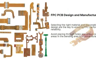
FPC PCB Design Guide for Flexible Printed Circuits
A practical FPC PCB design guide covering bend areas, copper, stiffeners, coverlay, stackup, assembly, and manufacturability for flexible printed circuits.
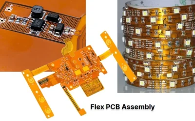
Flex PCBA Services: Lightweight, Durable, and Ready for Any Application
Highleap offers expert Flex PCB Assembly, ensuring precision, durability, and seamless integration for compact and complex devices.