
10 Layer AI Server PCB Engineering for Accelerator Hardware

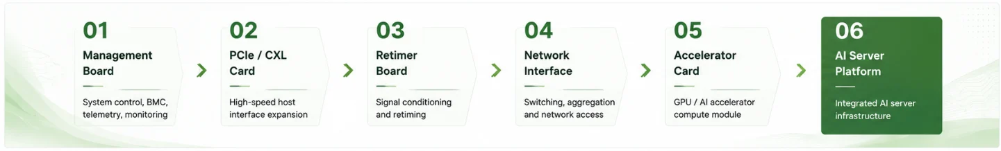
Figure 1. 10 layer AI server PCB for accelerator hardware.
Table of Contents
- Where a 10 Layer PCB Fits in AI Infrastructure
- Classify the Board Before Selecting the Stackup
- Accelerator Packaging, HBM and the PCB Boundary
- PCIe, CXL and Ethernet Channel Engineering
- Stackup, Material and Copper Decisions
- HDI, BGA Escape and Via Architecture
- Power-Delivery Network and Current Distribution
- Thermal and Mechanical Integration
- Reliability, Test and Traceability
- Fabrication Release and Quote Package
“AI server PCB” is a system description, not a fabrication class. The term can refer to a baseboard, accelerator add-in card, CXL memory device, retimer card, network interface, optical-module carrier, management controller, power-distribution board or a small control board inside a liquid-cooling subsystem. These products do not share one layer count, laminate, impedance tolerance, HDI buildup or reliability plan.
A ten-layer construction can be appropriate for selected AI-infrastructure boards, but it should not be advertised as a universal platform for high-end accelerator baseboards or switch systems. The correct layer count comes from component escape, channel count, reference-plane needs, power distribution, connector topology, mechanical thickness and qualification requirements. In many cases, a twelve-, sixteen- or higher-layer conventional board is lower risk than forcing several sequential HDI cycles and fragmented power planes into ten layers.
This guide explains where ten layers are technically credible and what must be supplied before fabrication. It intentionally avoids fixed claims such as “Tachyon equals six inches,” “0.4 mm BGA always requires 3+4+3,” or “all AI boards require Class 3.” Those decisions belong to the released channel model, package escape study and procurement documents. General construction guidance is available in the 10 layer PCB engineering overview, while detailed electrical work is covered by the high-speed channel guide.
Where a 10 Layer PCB Fits in AI Infrastructure
Ten layers are most credible when the board has a limited number of high-speed interfaces, a compact routing region and a power architecture that does not require many broad, isolated planes. Examples include management and BMC boards, accelerator or storage add-in cards with a controlled number of PCIe or CXL lanes, retimer cards, optical-module breakout cards, CXL memory expansion devices, network interface subassemblies, fan and pump controllers, telemetry boards and selected power-control products.
The same layer count becomes difficult when the board must escape multiple very large packages, carry many memory channels, route numerous 112 Gb/s or emerging 224 Gb/s-class lanes, support several high-current rails, or connect multiple high-density mezzanine and optical interfaces. In those cases, the routing and plane area consumed by antipads, via fields and power islands can make ten layers electrically fragile even when the traces can be made to fit.
| Board category | Why ten layers may work | Signals that more layers may be safer |
|---|---|---|
| BMC, management and telemetry | Moderate routing density, many low-speed controls, a small number of Ethernet, USB or PCIe links, and manageable power domains. | Large connector count, extensive isolation, mixed analog acquisition or multiple redundant management fabrics. |
| PCIe/CXL add-in or retimer card | A defined connector-to-device channel, controlled transition count and localized power conversion. | Several x16 links, large memory devices, many retimers, wide sideband interfaces or insufficient plane area around the connector and package. |
| Network or optical-module carrier | Short ASIC/retimer-to-module paths with a small number of lane groups and carefully modeled launches. | Many front-panel ports, long electrical reaches, dense 112G/224G-class lane fields or several connector transitions. |
| Accelerator add-in card | A package with a manageable pin map, package-level memory, limited external interfaces and a power design that can be implemented without sacrificing references. | Multiple accelerators, external memory buses, numerous chip-to-chip links, very high current, broad keepouts or extensive mechanical hardware. |
| Power and cooling control | Mixed power-control, sensing and communications functions may benefit from dedicated planes and isolation. | High-voltage spacing, very heavy copper, busbars or metal-backed thermal structures may call for a different construction rather than more signal layers. |
The decision should compare at least three architectures: a conventional ten-layer board, a ten-layer HDI board and a higher-layer conventional board. The lowest layer count is not automatically the lowest cost or the most reliable. Sequential lamination, laser drilling, copper filling and reduced yield can outweigh the cost of another pair of conventional layers.
Classify the Board Before Selecting the Stackup
The stackup should be selected from the board’s role in the system. An accelerator add-in card, CXL memory card and optical-module carrier may all be called AI hardware, but their critical constraints are different.
Management and control boards
These boards are commonly dominated by microcontrollers, BMC devices, power sequencing, fan or pump control, sensor interfaces and moderate-speed networking. A reference-plane-rich ten-layer stackup can provide clean return paths, isolation between switching power and measurement circuits, and sufficient power distribution without using premium low-loss material across the entire board.
PCIe and CXL devices
PCI Express and CXL links share a physical-layer foundation, but the governing revision and form factor still matter. PCIe 5.0 uses 32 GT/s NRZ, PCIe 6.0 uses 64 GT/s PAM4, and PCIe 7.0 Version 1.0 was released at 128 GT/s PAM4. CXL 4.0 was released in 2025. These facts establish signaling context; they do not provide a universal board loss budget. The applicable base specification, add-in-card or custom topology, connector model, retimer placement and package allocation must be identified before the board construction is selected.
Network and optical interconnect boards
IEEE 802.3df-2024 standardized 400 Gb/s and 800 Gb/s Ethernet objectives and physical layers. A board described as “800G” can still use different lane counts, electrical reaches, connectors and optical-module interfaces. At this revision, IEEE P802.3dj is still developing 1.6 Tb/s operation and further 200/400/800 Gb/s physical layers; designs using that work must name the exact draft or customer requirement. Similarly, OIF 224G-class projects distinguish extra-short, very-short, medium and long reach instead of defining one universal PCB channel.
For all three board types, the supplier needs the actual channel definition. A marketing label such as “Gen7,” “800G” or “224G” is not enough to release a laminate or back-drill process.
Accelerator Packaging, HBM and the PCB Boundary
High-bandwidth memory used by modern accelerators is normally integrated with the processor through an advanced package, interposer or package-level substrate. The HBM interface is therefore not generally routed as a conventional differential bus across the server PCB. The board carries the accelerator package’s external power, PCIe/CXL, chip-to-chip, management, clock and service interfaces. Treating HBM lanes as ordinary PCB stripline is a fundamental architecture error.
The package boundary changes the PCB problem in two ways. First, the board may not carry the ultra-wide HBM interface, but it must still support a very dense BGA escape and a high-current power-delivery network. Second, package escape, socket or land geometry and decoupling placement may dominate layer count even when the number of external high-speed lanes is modest.
Package information required for board planning
- ball map, pitch, land diameter and depopulation pattern;
- power and ground ball distribution by rail;
- external high-speed lane locations and reference-ball pattern;
- allowed fanout, via-in-pad and back-side decoupling zones;
- mechanical keepouts, stiffener, heatsink or cold-plate mounting;
- package and breakout models for channel simulation;
- assembly profile and coplanarity requirements.
A ten-layer design should be rejected early if the BGA escape study consumes the reference planes, fragments the power distribution or requires more buildup levels than the qualification plan can support. The 10 layer HDI engineering guide explains why pitch alone cannot determine 1+8+1, 2+6+2 or 3+4+3.

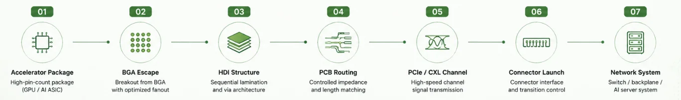
Figure 2. 10 layer AI server PCB fabrication and signal integrity.
PCIe, CXL and Ethernet Channel Engineering
High-speed feasibility must be established from the complete channel: package breakout, via transition, routed line, connector or cable launch, retimer if present and receiver package. Material selection is only one variable.
| Channel element | Required engineering input | Fabrication implication |
|---|---|---|
| Transmission line | Target impedance, frequency-dependent loss allocation, maximum reach and crosstalk limit. | Material construction, copper profile, dielectric thickness, finished width/gap and coupon design. |
| BGA or connector breakout | Pad, antipad, reference pins, neck-down length and local return-current path. | Minimum geometry, registration, mask clearance, via span and possible HDI requirement. |
| Via transition | 3D model or validated library including unused stub and ground-via arrangement. | Back-drill, blind via, pad/antipad, controlled depth and inspection method. |
| Connector/module launch | Vendor model, board thickness, reference geometry and fixture boundary. | Local plane cutouts, via field, finished copper, plating and dimensional tolerance. |
| Retimer placement | Two separate channel budgets, reference clocks and power/noise requirements. | Additional package escape, power planes, decoupling and thermal area. |
Back-drilling should be specified when the extracted unused stub violates the channel requirement and a blind-via solution is not preferable. The note must define drill side, target layer, maximum residual stub, tool diameter, allowed breakout and verification method. A fixed “3 mil maximum” claim is not appropriate for every panel thickness and registration window.
Likewise, differential-pair matching and lane spacing should come from the governing implementation and channel model. Rules such as +/-1 mil intra-pair or 10W spacing are not universal indicators of compliance. The routing guide explains how to convert timing, crosstalk and transition requirements into layout constraints.
Stackup, Material and Copper Decisions
A practical ten-layer AI-infrastructure stackup often favors reference planes over maximum signal-layer count. A four-signal, four-ground, two-power architecture can provide two outer microstrip layers and two well-referenced stripline layers while retaining broad power distribution. Six-signal/four-plane arrangements provide more routing capacity but can create adjacent signal layers or inadequate plane area; they should be used only when the actual return-path and crosstalk plan supports them.
Low-loss material should be placed where the channel model shows that it is needed. A hybrid build may use a low-loss core and bond system around selected high-speed stripline layers while using another compatible system elsewhere. The hybrid construction must still satisfy bonding, drilling, dimensional movement, copper adhesion and thermal-cycle requirements. Two laminate families in the same marketing loss class are not automatically interchangeable.
Material release inputs
- exact approved grade or approved-material list;
- core and prepreg construction, resin content and glass style;
- copper profile used in the insertion-loss model;
- design Dk and Df source, method and frequency range;
- substitution authority and requalification path;
- thermal history from sequential lamination, via filling, finish and assembly;
- availability, minimum purchase quantity and long-term supply constraints.
The 10 layer material guide covers these controls in detail. Controlled impedance must be recalculated against the proposed production construction, not copied from a generic 5 mil/50 Ω table.
HDI, BGA Escape and Via Architecture
HDI is justified when it creates routing access or electrical performance that a conventional via field cannot provide. The package pin map, number of rows, power-via demand and available signal layers matter more than pitch by itself.
For accelerator, retimer and switch packages, via-in-pad may be used to recover breakout channels. The fabrication drawing should distinguish copper-filled microvia, nonconductive fill, resin plug, planarization and copper cap. Stacked microvias require structure-specific reliability evidence because the interface between filled vias and target lands can become a fatigue location under repeated thermal exposure.
Any-layer or multiple-buildup HDI should not be selected merely because it is available. Each buildup level adds imaging, lamination, laser drilling, metallization and often copper fill/planarization. The design should compare a higher-layer conventional board against a complex ten-layer HDI board using routing, yield, reliability and cost-not only nominal layer count.
HDI release checks
- show every blind, buried, skip and through-via span in the drill table;
- identify stacked and staggered relationships by layer;
- confirm microvia diameter, dielectric thickness and capture land as one process window;
- define fill, cap, dimple and assembly-surface requirements;
- state product specification, class, qualification coupon and lot-acceptance requirements;
- do not invoke IPC-6016 as a current HDI acceptance standard; use the applicable current product specification and procurement revision.
Power-Delivery Network and Current Distribution
Accelerator power cannot be designed from a current headline alone. The board PDN must satisfy DC voltage drop, transient impedance, converter placement, package entry, connector or busbar limits, copper temperature rise and mechanical constraints. Current may be delivered through edge contacts, high-current connectors, busbars, vertical power modules or local regulators; each architecture uses the PCB differently.
The target-impedance relationship Ztarget = ΔV / ΔI is a starting point, not a complete PDN specification. The relevant transient spectrum, voltage-regulator control loop, package capacitance and allowed droop must be defined. Above the frequency range where board-mounted capacitors remain effective, package and on-die structures dominate.
DC and AC questions that affect fabrication
- Which rails require broad planes, heavy copper, copper inlay or external conductors?
- What is the minimum finished copper thickness, rather than nominal foil weight?
- How much plane area is lost to antipads, slots, thermal cutouts and mounting hardware?
- Where can back-side decoupling be placed, and are filled vias required in component lands?
- What voltage drop and temperature rise are permitted at worst-case current and ambient?
- Does the board need current-sense structures, calibrated shunts or Kelvin routing?
IPC-2152 provides guidance for current-carrying capacity and thermal behavior, but it does not reduce a complex plane or via field to one universal current-density limit. Use simulation or validated test data for high-current accelerator boards. In some products, a busbar, leadframe or power module is more appropriate than forcing hundreds of amperes through ordinary PCB planes.
Thermal and Mechanical Integration
The PCB is one element of the thermal path. High-power packages usually reject most heat through the package lid, heatsink or liquid cold plate rather than through the board. Copper planes and vias can spread local heat and reduce electrical loss, but a simple via-count calculation does not prove package thermal performance.
Mechanical loading can be as important as thermal conductivity. Large packages, stiffeners, cold plates and connector cages create bending moments that can strain solder joints and microvias. The board drawing should define thickness, flatness, keepouts, mounting-hole tolerances and any controlled local thickness. Assembly analysis should consider warpage through reflow and service temperature.
Thermal/mechanical release inputs
- package power and approved thermal interface;
- heatsink or cold-plate attachment and clamping load;
- component and via keepouts under mechanical hardware;
- board support, stiffener and chassis constraints;
- allowed bow/twist and local coplanarity;
- temperature range and expected thermal cycles;
- material CTE and hybrid-stack symmetry.
Heavy copper changes etch geometry, resin fill and lamination behavior. Copper coins and inlays are special constructions that require explicit dimensions, bonding method, flatness and inspection criteria; they should not be presented as standard options on every AI board.
Reliability, Test and Traceability
Data-center use does not automatically mean IPC Class 3, and a commercial AI product does not inherit automotive, medical or aerospace certification from the word “AI.” The applicable performance class and quality system come from product risk, customer requirements and procurement documentation.
For rigid boards, IPC-6012 is normally the relevant product performance family; rigid-flex boards use IPC-6013, and high-frequency constructions may invoke IPC-6018 where applicable. IPC-A-600 provides visual interpretation but does not replace the product specification. The revision, class, addenda and customer exceptions must be stated on the order.
Reliability evidence may include thermal-stress microsections, interconnect stress testing, HATS, temperature cycling, reflow simulation, CAF testing, insertion-loss coupons or product-level environmental qualification. These methods answer different questions. JEDEC component test methods do not automatically define bare-board lot acceptance, and IST is not simply a −40 deg C to +125 deg C chamber cycle.
Records commonly considered for high-risk programs
- certificate of conformance and electrical-test confirmation;
- released stackup and material/lot traceability;
- TDR results for specified impedance coupons;
- microsection results for the structures and sample plan ordered;
- controlled-depth or back-drill verification where required;
- first-article or qualification reports for new HDI structures;
- serialization and process-traveler traceability when contractually required.
Not every shipment needs every report. The quote should distinguish standard records, optional reports, destructive testing and qualification work that requires dedicated coupons or extra panels.
Fabrication Release and Quote Package
A useful quotation cannot be produced from “10 layer AI server board” and an outline. The supplier needs enough information to distinguish a management board from a high-speed retimer or accelerator card and to identify where process risk is concentrated.
| Release item | Minimum content |
|---|---|
| Fabrication data | ODB++, IPC-2581 or Gerber/NC data, netlist, outline, panel or delivery-array requirements and revision identifiers. |
| Stackup/material | Layer functions, finished thickness, copper, material policy, approved substitutions and controlled structures. |
| Via architecture | Drill chart by start/stop layer, fill/cap requirements, back-drill drawing and controlled-depth tolerances. |
| Electrical requirements | Impedance table, channel or loss-coupon requirements, applicable interface revision and any supplier artwork authority. |
| Quality plan | Product specification, class, addenda, sample plan, qualification tests, shipment records and traceability period. |
| Commercial inputs | Quantity, schedule basis, material availability, tooling/NRE separation, delivery terms, packaging and forecast assumptions. |
The DFM response should return the proposed production stackup, finished impedance geometry, identified exceptions, special-process assumptions and approval items. A quotation that silently substitutes material, changes the via architecture or removes a required report is not technically equivalent.

Recommended Posts

Taconic RF-35 PCB Manufacturing Service — Prototype Through Volume Production
Figure 1. Taconic RF-35 PCBTaconic RF-35 is the workhorse...

Isola Astra MT77 PCB Manufacturing
Figure 1. Isola Astra MT77 PCB ManufacturingIsola Astra...

Custom Rogers RO4835 PCB Fabrication & Assembly Services
Figure 1. Rogers RO4835 PCBRogers RO4835 PCB is a...

Nelco N4000-13 PCB Material and Manufacturing Guide | Highleap Electronics
Figure 1. Nelco N4000-13 PCBNelco N4000-13 PCB is a...
How to get a quote for PCBs
Let’s run DFM/DFA analysis for you and get back to you with a report. You can upload your files securely through our website. We require the following information in order to give you a quote:
-
- Gerber, ODB++, or .pcb, spec.
- BOM list if you require assembly
- Quantity
- Turn time
For PCBA services, please provide your BOM (Bill of Materials) and any specific assembly instructions. We also offer DFM/DFA analysis to optimize your designs for manufacturability and assembly, ensuring a smooth production process.