
Centroid File for PCB Assembly Used in SMT Manufacturing

Table of Contents
At Highleap Electronics, we review centroid (placement/XY) files every day for PCB manufacturing and SMT assembly. A centroid export is only correct when it matches the production dataset. That means the Gerber outline, drill data, BOM revision, and any panelization rules must be from the same build package.
This guide explains how to generate centroid data that is clear, consistent, and ready for factory programming. It follows the same practical rules as our pick-and-place-file-requirements specification—because centroid files and pick-and-place files are often the same placement dataset under different names.
What a centroid file is
A centroid file is also called a component placement file, XY file, or pick-and-place file. It tells the SMT pick and place machine the center location (or a defined pickup point) of each component, its rotation, and whether it is placed on the Top or Bottom side of the PCB.
During NPI or first builds, the assembler typically cross-checks the centroid file against the Gerbers (outline + pads) and the BOM to confirm the coordinates and orientations match the exact board revision being assembled.
Centroid file and pick and place file
Many CAD tools use the terms centroid and pick and place interchangeably. In practice, both usually contain the same core columns: RefDes, X, Y, Rotation, and Side. Differences are often just headers, column naming, or the export template.
If you need a clear baseline for formatting and conventions, refer to our pick-and-place-file-requirements guide.
Why centroid accuracy matters
Centroid errors become placement errors. On small passives and fine-pitch packages, even a small offset can increase tombstoning, skew, bridging, and AOI false calls. The tighter the pitch, the more sensitive the build is to coordinate and rotation accuracy.
| Component type | Typical placement accuracy (machine/process dependent) |
|---|---|
| 0402 passives | Often within ±0.05–0.10 mm (indicative) |
| 0201 passives | Often within ±0.03–0.06 mm (indicative) |
| 0.5 mm pitch QFP | Often within ±0.05–0.10 mm (indicative) |
| 0.4 mm pitch BGA | Often within ±0.03–0.08 mm (indicative) |
Note: The ranges above are indicative only. Actual placement capability depends on machine model, board size, fiducials, stencil/paste control, and process tuning.
Centroid file format requirements
A factory-ready centroid file should be machine-readable and unambiguous. CSV and tab-delimited TXT are both widely accepted. What matters most is consistent columns, numeric-only coordinate fields, and clear notes for units, origin, and rotation convention.
For best compatibility, align your export with pick-and-place-file-requirements: make the data self-explanatory even when the file is opened outside your CAD tool.
Required columns
- Reference designator (RefDes) must match the BOM
- X location numeric coordinate from the defined origin
- Y location numeric coordinate from the defined origin
- Rotation numeric degrees with a documented convention
- Side Top or Bottom
Recommended columns
- Value or description helps the factory confirm part class quickly
- Package or footprint helps identify feeders and nozzles
- MPN optional but helpful for kitting and ambiguity reduction
Header notes to include
- Units mm or mil (mm is preferred)
- Origin lower-left corner of board outline or board center—state it clearly
- Coordinate meaning component centroid vs pickup point—state it clearly
- Rotation direction many systems use CCW positive, but confirm your CAD export
- Rotation range 0–360 (avoid negative angles unless you explicitly document it)
- Bottom-side behavior specify if Bottom data is mirrored or not
- Board revision must match Gerbers and BOM revision
# Centroid File - Board Rev A
# Units: Millimeters
# Origin: Lower-left corner of board outline
# Coordinates represent: Component centroid (center of footprint)
# Rotation: Counterclockwise positive, 0–360
# Bottom data: Not manually mirrored (handled by import tool if needed)
#
RefDes,X(mm),Y(mm),Rotation(deg),Side,Value,Package,MPN
C1,5.080,12.700,0,Top,100nF,0603,CL10B104KB8NNNC
C2,7.620,12.700,0,Top,1uF,0603,GRM188R61E105KA12D
R1,10.160,15.240,90,Top,10K,0402,RC0402FR-0710KL
U1,25.400,20.320,0,Top,MCU,LQFP48,STM32F103C8T6
U2,35.560,20.320,180,Bottom,Driver,QFN-16,EXAMPLE-MPN
Coordinate precision
- Minimum 3 decimal places (mm)
- Recommended 4 decimal places for dense SMT
- Practical limit 6 decimal places—beyond this is rarely meaningful
If you are preparing a complete handoff package beyond centroid files—including Gerbers, drill, BOM, and drawings—use this checklist to avoid missing items: Complete assembly file requirements.
How centroid coordinates are determined
Most CAD tools export centroid coordinates from the footprint library definition. If the footprint origin or pickup point is defined incorrectly, the centroid can be offset even when the pads look correct in the editor. Understanding the common centroid logic helps you catch library issues early—before they become assembly programming issues.
Two-pad components
For symmetric chip parts, the centroid is usually the midpoint between pad centers:
X_centroid = (X_pad1 + X_pad2) / 2
Y_centroid = (Y_pad1 + Y_pad2) / 2
Multi-pin ICs
For common QFP, QFN, and SOIC footprints, the centroid is typically the geometric center of the pad array (or defined body center). Problems usually come from footprint origin placement or inconsistent library conventions.
- Footprint origin set to a corner instead of the body center
- Library built from a different reference (courtyard vs body vs pad array center)
- Incorrect pickup point on odd-shape parts
BGAs
For BGAs, the centroid is typically the center of the ball array, often the midpoint between opposite corners:
X_centroid = (X_A1 + X_corner_opposite) / 2
Y_centroid = (Y_A1 + Y_corner_opposite) / 2
Connectors and odd-form components
For non-symmetric components, the best placement point may be the datasheet pickup location rather than the geometric body center. This is common for large connectors, modules, shields, and parts with asymmetric mass distribution. If the datasheet specifies a pickup point, use it and document it in the header notes.
Rotation polarity and special parts
Even with correct X and Y coordinates, rotation problems can stop a build. Assemblers typically verify rotation by checking a small set of anchor parts: one IC for Pin 1, one polarized device, and at least one bottom-side part to confirm the mirroring behavior.
Rotation convention and zero reference
- Rotation direction is often counterclockwise positive, but not universal
- Zero reference is defined by the footprint library default orientation
- Do not “fix” rotations in Excel; correct the library/export rules and regenerate
- Bottom-side parts may require mirroring depending on CAD export settings and the factory import tool
Polarized components
- ICs confirm Pin 1 orientation matches the PCB marking and package indicator
- Diodes and TVS confirm the cathode stripe matches the land pattern and silkscreen
- Electrolytics and tantalum confirm polarity marks match pad polarity
LEDs press-fit parts and fiducials
- LEDs centroid at body center; rotation defines anode/cathode orientation
- Press-fit connectors include only if machine-placed; note any special handling
- Fiducials use the true fiducial center; rotation set to 0
For broader PCB assembly design guidance—including fiducials, tooling rails, keep-outs, and panel rules—see Assembly design rules.
How to validate a centroid file
A simple, repeatable validation routine catches most centroid-related issues before production. Focus first on systematic errors such as origin, units, and rotation convention. Then look for isolated footprint problems.
Visual overlay check
- Overlay centroid points on Gerber outline and copper pads (assembly layer helps)
- Check corner components first to catch origin mismatch quickly
- Verify at least one part in each category: passives, ICs, polarized parts, bottom-side parts
Automated checks
- Compare component count against the BOM (placed parts only)
- Verify all coordinates fall within the board outline
- Check for duplicate coordinates (can indicate stacked parts, fiducials, or export issues)
- Sanity-check rotation values and look for unusual angles
First article feedback loop
- Inspect placement after the first run and measure any systematic offset
- Document corrections and update CAD export settings or library definitions
- Regenerate the centroid file from the same revision as the Gerbers and BOM
Recommended handoff package naming (avoids revision mismatch)
- ProjectName_RevA_Gerber.zip
- ProjectName_RevA_Drill.zip (or included in Gerber zip)
- ProjectName_RevA_BOM.xlsx
- ProjectName_RevA_Centroid.csv
- ProjectName_RevA_AssemblyDrawings.pdf
If you want an extra safety step for dense boards, new footprints, or first-time builds, our engineers can review origin, units, and rotation conventions before production: Free DFM review.
Contact Highleap Electronics for centroid file questions or validation assistance—especially if you are unsure about origin definition, unit settings, or bottom-side rotation behavior.

Recommended Posts

Wireless Mechanical Keyboard PCB Manufacturing
Table of contentsWireless Keyboard PCB Procurement...

Split Keyboard PCB Manufacturing & Assembly
Table of contentsSplit Keyboard PCBA Procurement...
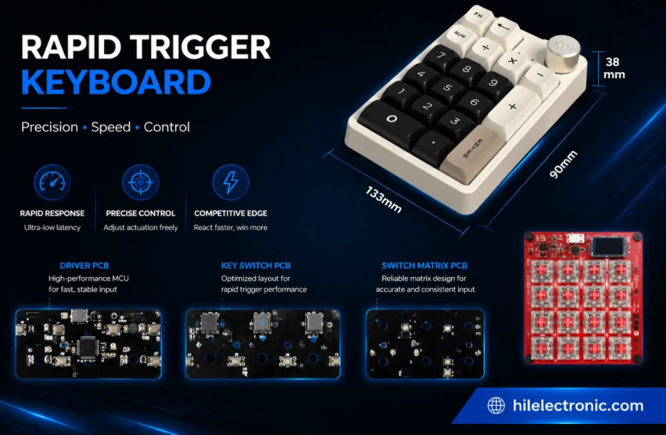
Rapid Trigger Keyboard PCB Manufacturing & PCBA
Table of contentsRapid Trigger PCBA Buying and Performance...
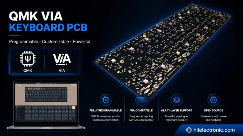
QMK/VIA Keyboard PCB Manufacturing & Assembly
Table of contentsQMK/VIA Keyboard PCB Buying...
How to get a quote for PCBs
Let us run DFM/DFA analysis for you and get back to you with a report.
You can upload your files securely through our website.
We require the following information in order to give you a quote:
-
- Gerber, ODB++, or .pcb, spec.
- BOM list if you require assembly
- Quantity
- Turn time
In addition to PCB manufacturing, we offer a comprehensive range of electronic services, including PCB design, PCBA (Printed Circuit Board Assembly), and turnkey solutions. Whether you need help with prototyping, design verification, component sourcing, or mass production, we provide end-to-end support to ensure your project’s success. For PCBA services, please provide your BOM (Bill of Materials) and any specific assembly instructions. We also offer DFM/DFA analysis to optimize your designs for manufacturability and assembly, ensuring a smooth production process.