
Rigid-Flex PCB Fabrication for Prototypes and Production

Rigid-flex PCB fabrication is the preferred solution when a product needs to save space, reduce connectors, improve vibration resistance, and fit electronics into folded or three-dimensional mechanical structures. By combining rigid FR4 sections with flexible polyimide circuits in one integrated assembly, rigid-flex boards reduce wiring complexity, improve packaging efficiency, and eliminate many of the interconnect failures found in cable-and-connector designs.
For medical devices, automotive electronics, industrial controls, aerospace systems, cameras, wearables, and other compact products, rigid-flex technology helps engineers solve layout and reliability problems that standard rigid boards cannot. At Highleap, we support prototype PCB manufacturing and volume rigid-flex production with engineering review focused on bend reliability, stack-up feasibility, impedance requirements, and assembly readiness.
Compared with standard PCB builds, rigid-flex fabrication requires tighter control over materials, lamination, transition zones, drilling, and handling. A design that looks electrically correct can still fail if bend areas, via placement, or flex construction are not optimized for manufacturing. That is why early PCB DFM review is essential before production begins.
Table of Contents
Why Choose Rigid-Flex PCB Fabrication
Rigid-flex PCBs are used when a product design needs more than a flat board connected by cables. Instead of linking multiple rigid boards with connectors or wire harnesses, rigid-flex integrates those sections into one structure that can fold, bend, and fit into tight mechanical spaces. This improves reliability, reduces assembly complexity, and helps create smaller and lighter finished products.
For many OEMs, the advantage is not just electrical integration. It is also about reducing failure points, simplifying final assembly, and building products that survive movement, shock, and vibration more effectively than traditional multi-board assemblies. That is why rigid-flex is widely used in high-reliability and space-constrained applications.
- Fewer connectors and solder joints: helps reduce common field failure points.
- Better use of internal space: supports folded, stacked, and compact product layouts.
- Lower assembly complexity: reduces manual wiring and installation errors.
- Improved vibration resistance: integrated flex sections are more reliable than many cable assemblies.
- Weight reduction: important in portable, automotive, and aerospace electronics.
- Cleaner system design: fewer discrete interconnect parts can improve consistency from prototype to production.
Rigid-flex is especially valuable when connector reliability, enclosure size, mechanical movement, or system weight are design constraints. If your application requires complex packaging or long-term mechanical reliability, rigid-flex PCB fabrication is often the better choice over separate rigid boards and interconnect cables.
Upload Your Rigid-Flex Files for DFM Review
Highleap’s Rigid-Flex PCB Capabilities
Choosing a rigid-flex supplier is not only about finding a factory that can laminate rigid and flexible materials together. It is about choosing a manufacturing partner that can control stack-up construction, rigid-to-flex transitions, drilling quality, plating consistency, material compatibility, and final handling of fragile flex sections.
Highleap provides custom PCB manufacturing services for rigid-flex projects from prototype through production. Our engineering team reviews stack-up structure, transition-zone design, copper selection, coverlay strategy, and bend-area risk before fabrication starts, helping customers avoid common problems that can delay builds or reduce yield.
| Capability | Support |
|---|---|
| Production stage | Prototype, NPI, low-volume, and mass production |
| Stack-up options | Custom rigid-flex constructions for simple and complex multilayer designs |
| Flex materials | Polyimide, adhesive and adhesiveless constructions |
| Rigid materials | Standard FR4, high-Tg options, and application-specific laminates |
| Copper options | ED and RA copper based on bend-life requirements |
| Special support | Controlled impedance, stiffeners, selective coverlay, complex outlines, and engineering review |
For designs with signal integrity requirements, we also support controlled impedance PCB structures and can coordinate stack-up recommendations with your target electrical performance. What customers typically value most is not just capability on paper, but the ability to receive clear engineering feedback before ordering.
How the Rigid-Flex Fabrication Process Works
Rigid-flex PCB fabrication combines flexible circuit processing and rigid multilayer PCB lamination into one controlled manufacturing flow. While each project depends on its layer count, materials, and application requirements, most builds follow the same core sequence:
- Flex core preparation: Flexible circuit layers are imaged, etched, cleaned, and inspected before being integrated into the final structure.
- Coverlay processing: Coverlay is applied to protect flex circuitry in bend areas and exposed flexible regions where standard solder mask is not suitable.
- Rigid material build-up: FR4 layers, prepregs, and copper foils are prepared around the flex core according to the defined stack-up.
- Lamination: Rigid and flexible materials are aligned and laminated together under controlled pressure and temperature to form a unified board structure.
- Drilling and plating: Through-holes are drilled and metallized to create electrical interconnection across the rigid-flex assembly.
- Outer-layer imaging and etching: Outer copper layers are patterned and etched to complete the required circuitry.
- Solder mask and surface finish: Rigid areas receive solder mask and the specified surface treatment, such as ENIG surface finish or other options based on assembly needs.
- Routing, release, inspection, and testing: The profile is routed, flex sections are released, and finished boards undergo inspection and electrical testing before shipment.
Although the production flow looks straightforward at a high level, rigid-flex builds are more sensitive than standard rigid PCBs because the board combines materials with different mechanical and thermal behavior. Lamination pressure, registration control, drilling quality, and handling of the flex sections all have a direct impact on final reliability.

Key Design Rules That Prevent Costly Failures
Most rigid-flex PCB failures do not start in the factory. They start in the design files. A board may be electrically correct but still fail during bending, assembly, or long-term use if the flex construction, transition zones, and material choices are not optimized for manufacturing.
- Keep bend areas as simple and thin as possible: unnecessary copper, extra layers, and complex structures reduce flex reliability.
- Avoid vias in dynamic flex zones: vias create stress concentration and should usually remain inside rigid sections or outside active bend areas.
- Protect the rigid-to-flex transition: this area needs careful structural and routing control to reduce the risk of cracking, delamination, and mechanical stress damage.
- Choose copper according to bend requirements: repeated movement usually requires more ductile copper constructions for better flex life.
- Review coverlay and stiffener strategy together: these features influence both manufacturability and assembly support.
- Design for assembly as well as fabrication: connector reinforcement, component stability, and handling strength should be considered from the start.
The most common rigid-flex risks include cracked traces, delamination, transition-zone weakness, registration problems, and assembly damage caused by insufficient mechanical support. These issues are much easier to prevent at the design review stage than after a board has already been built.
For that reason, every rigid-flex project should include early DFM review, complete build notes, and well-prepared production data.
Typical Applications for Rigid-Flex PCBs
Rigid-flex PCB fabrication is used in products that need compact packaging, higher mechanical reliability, or reduced interconnect complexity. It is particularly useful when electronics must fit into folded, stacked, hinged, or moving structures where ordinary rigid boards and discrete cables are not the ideal solution.
- Medical devices: handheld instruments, monitoring systems, diagnostic devices, and other compact medical electronics.
- Automotive electronics: cameras, control modules, compact sensing assemblies, and space-constrained vehicle electronics.
- Industrial equipment: control systems, sensors, embedded electronics, and high-reliability machine interfaces.
- Aerospace and defense: vibration-resistant and weight-sensitive electronics with demanding reliability requirements.
- Consumer and portable electronics: cameras, wearables, foldable devices, and miniaturized products that require efficient internal packaging.
- Robotics and motion systems: designs where controlled movement or repetitive flexing makes cable-based interconnection less desirable.
If your enclosure design forces the PCB into a non-flat form factor or requires improved interconnect reliability, rigid-flex is usually worth evaluating early. In many cases, the added fabrication complexity is justified by reduced assembly risk and better long-term field performance.
What Files We Need for an Accurate Quote
The fastest way to get a useful rigid-flex quote is to provide more than Gerber files alone. Because rigid-flex boards combine both electrical and mechanical requirements, the quotation package should clearly show how the board is built, where it bends, and what performance targets it must meet.
- Gerber files or ODB++ data: complete production data for copper layers, mask, drill, and outline.
- Stack-up drawing: a clear view of rigid and flex layer construction, material preferences, and thickness targets.
- Mechanical drawing: profile dimensions, bend areas, keep-out regions, and critical tolerances.
- Bending information: whether the flex is static or dynamic, plus bend radius if already defined.
- Fabrication notes: copper weight, surface finish, impedance requirements, material requests, and IPC class.
- Quantity and schedule: expected prototype quantity, production volume, and target lead time.
Our engineering team reviews the package for stack-up feasibility, rigid-to-flex transition quality, via placement in relation to bend areas, copper suitability, and manufacturing risks that could delay fabrication or reduce yield. This review helps convert a quote request into practical feedback rather than just a price.
If you are preparing a new project, you can submit your files through our PCB quote page or explore full PCB manufacturing services for production planning.
Get a Quote for Your Rigid-Flex PCB Project
Rigid-Flex PCB Fabrication FAQ
What is the difference between rigid-flex PCB fabrication and flex PCB with stiffeners?
A true rigid-flex PCB integrates rigid and flexible sections into one laminated structure with electrical interconnection across the build. A flex PCB with stiffeners adds mechanical reinforcement, but it does not create the same integrated rigid-flex construction.
Is rigid-flex PCB fabrication suitable for prototypes?
Yes. Prototype builds are often the best way to verify bend behavior, mechanical fit, stack-up feasibility, and assembly support before volume production. This is why many customers begin with prototype PCB manufacturing before releasing a larger order.
What causes rigid-flex PCB failures most often?
The most common causes include poor bend-zone design, vias placed too close to flex areas, weak rigid-to-flex transitions, material mismatch, and incomplete fabrication documentation.
Can you help optimize a rigid-flex design before fabrication?
Yes. Our engineering team can review stack-up structure, transition zones, bend requirements, and manufacturability risks before the design enters production.
What files should I send for a rigid-flex quote?
We recommend sending Gerber or ODB++ files, stack-up information, mechanical drawings, bend requirements, fabrication notes, and target quantities for prototype or production. You can submit these through our quote request page.
When is rigid-flex the better choice than standard rigid PCBs?
Rigid-flex is often the better choice when a product needs compact packaging, reduced connector count, improved vibration resistance, or a folded internal layout. If the product does not need bending or 3D packaging, a standard rigid PCB may be more cost-effective.
Can rigid-flex boards support special finishes and advanced structures?
Yes. Depending on the design, rigid-flex boards can support finishes such as ENIG, as well as advanced routing and structure options depending on the mechanical design, electrical needs, and manufacturing constraints.
Sabrina has over 18 years of experience in the PCB industry, with a strong background in CAM engineering and PCB file review. She supports PCB projects from prototype to volume production, focusing on manufacturability and process reliability. Her work helps engineering teams reduce production risk and achieve stable, high-quality PCB manufacturing results.

Recommended Posts
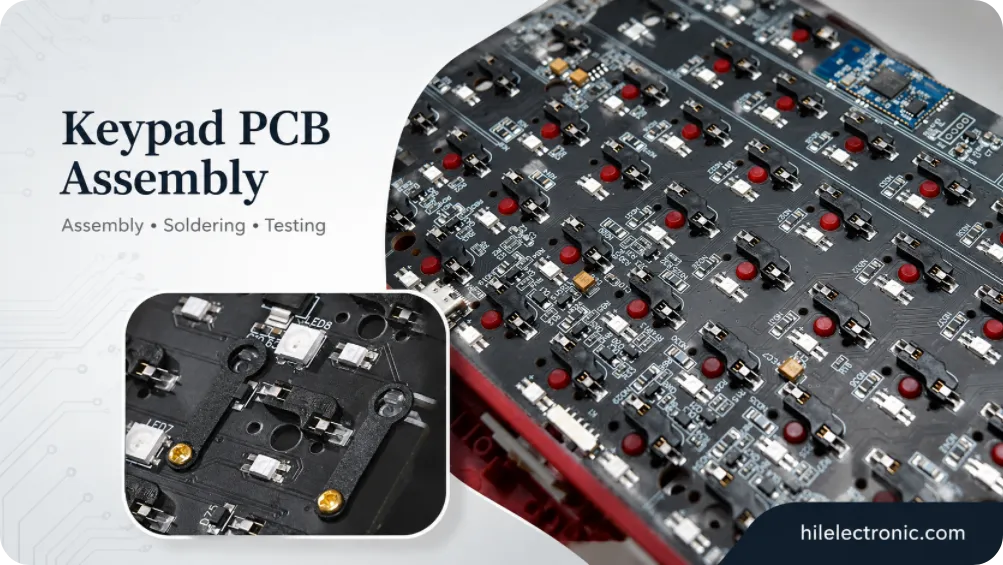
Keypad PCB Assembly Manufacturer | Custom Control Keypads
A keypad PCB assembly manufacturer may be building a...
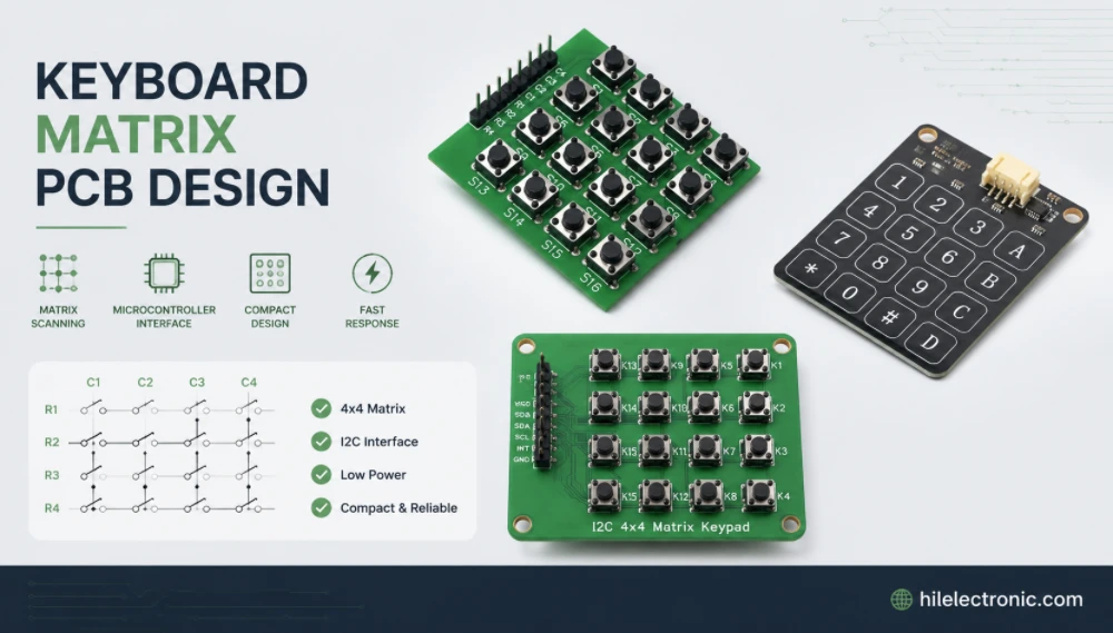
Keyboard Matrix PCB Design & Manufacturing | Anti-Ghosting
Keyboard matrix PCB design converts a large number of...
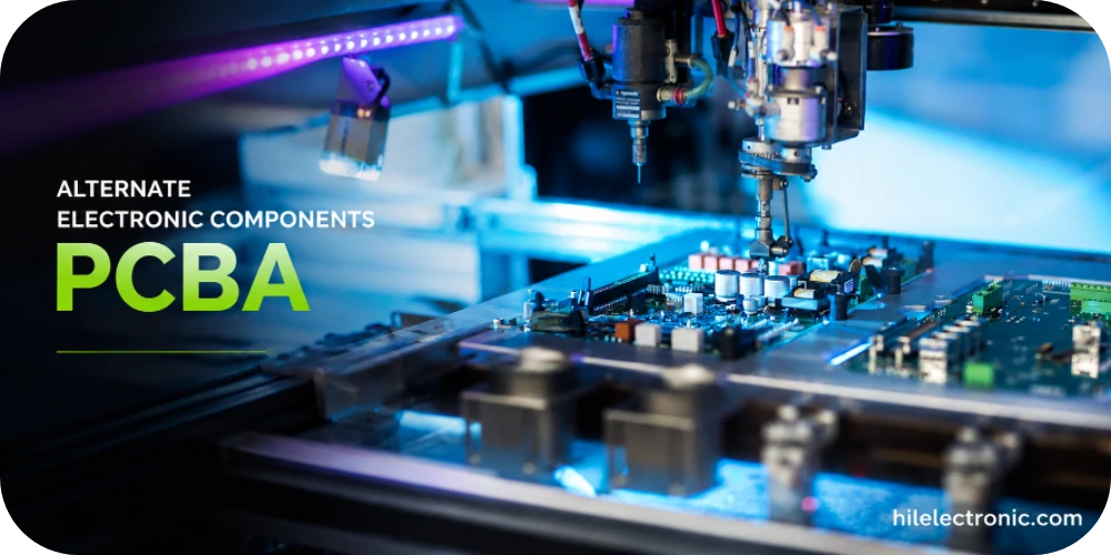
Alternate Electronic Components PCBA: Selection, Approval and Production Validation
Alternate electronic components can protect a PCB assembly...

Electronic Component Lead Times PCBA Solutions
Electronic component lead times determine whether a PCB...
How to get a quote for PCBs
Let us run DFM/DFA analysis for you and get back to you with a report.
You can upload your files securely through our website.
We require the following information in order to give you a quote:
-
- Gerber, ODB++, or .pcb, spec.
- BOM list if you require assembly
- Quantity
- Turn time
In addition to PCB manufacturing, we offer a comprehensive range of electronic services, including PCB design, PCBA (Printed Circuit Board Assembly), and turnkey solutions. Whether you need help with prototyping, design verification, component sourcing, or mass production, we provide end-to-end support to ensure your project’s success. For PCBA services, please provide your BOM (Bill of Materials) and any specific assembly instructions. We also offer DFM/DFA analysis to optimize your designs for manufacturability and assembly, ensuring a smooth production process.