
Shengyi S1000-2M PCB for High-Layer-Count Lead-Free Reliability
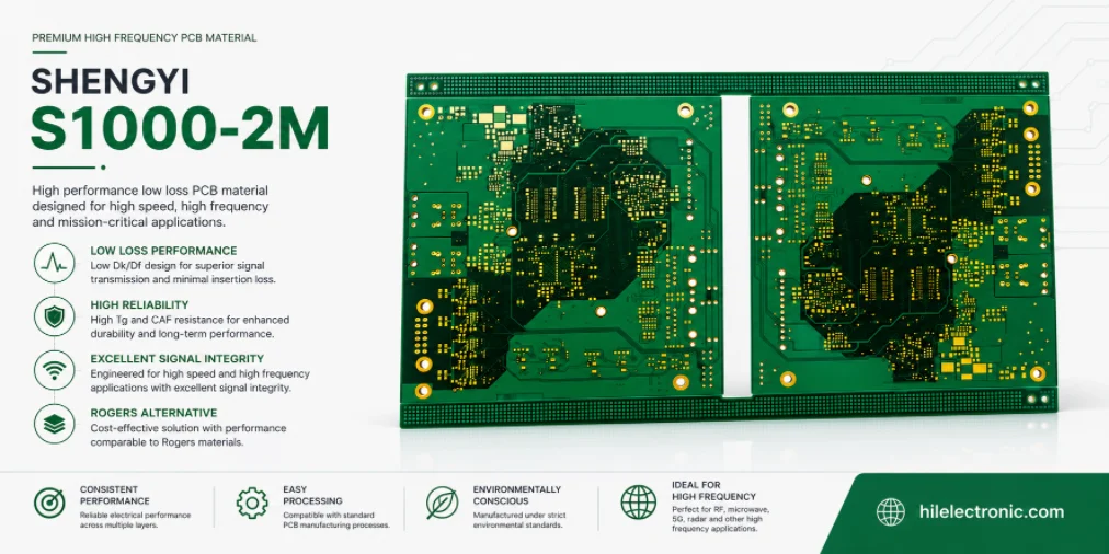
Shengyi S1000-2M is a high-Tg, low-CTE FR-4.0 laminate designed for high-layer-count boards that must survive lead-free processing and maintain plated-through-hole reliability. Shengyi highlights high heat resistance, low z-axis expansion, anti-CAF capability, low water absorption, mechanical processability, and suitability for computer, communication, automotive, and high-multilayer applications.
The material should not be sold as an ultra-low-loss laminate. Its official datasheet lists typical Dk 4.6 and loss tangent 0.018 at 1 GHz for the specified reference specimen. The correct value proposition is mechanical and thermal reliability: 180°C Tg by DSC, 185°C by DMA, 355°C Td, T288 of 30 minutes, 41 ppm/°C z-axis CTE below Tg, 208 ppm/°C above Tg, and 2.4% total z expansion from 50–260°C.
Those properties are useful for thick multilayers, but reliable holes still require conservative aspect ratio, controlled drilling and desmear, uniform plating, copper balance, and a defined assembly thermal history.
Why S1000-2M Fits High-Layer Reliability
Layer count magnifies every dimensional and thermal variable. More layers mean more registration interfaces, more copper imbalance opportunities, thicker finished boards, longer through-hole barrels, and often smaller pads and antipads. During lead-free reflow, the resin expands through the z axis while the copper barrel resists that movement. Repeated strain can create fatigue cracks.
S1000-2M addresses this mechanism with lower z-axis CTE and strong time-to-delamination performance. Shengyi also identifies excellent through-hole reliability and anti-CAF performance as key features.
Where the material is most useful
S1000-2M is a strong candidate for:
- thick industrial and telecom multilayers;
- server, storage, and communication control boards where ultra-low loss is not required;
- automotive electronics with repeated thermal exposure;
- boards with many plated through holes and connectors;
- lead-free assemblies with multiple reflow cycles;
- high-layer products requiring a widely processable FR-4.0 system.
The material should be selected as part of multilayer reliability controls, not as a single-property upgrade.
Why higher Tg is not enough
A high Tg delays the point at which resin expansion changes sharply, but the absolute CTE values, total expansion, cure state, moisture, and fracture behavior are equally important. The finished board geometry can outweigh the material advantage. A very thick board with small holes and insufficient barrel copper can still fail after reflow.
Material Snapshot for Stackup Release
The values below come from Shengyi’s official S1000-2M datasheet and are typical reference values based on a 1.6 mm 8×7628 specimen.
| Property | Typical value | Engineering relevance |
|---|---|---|
| Material class | FR-4.0 high-Tg, high-performance, low-CTE laminate | Reliability-focused multilayer material |
| Tg by DSC / DMA | 180°C / 185°C | Supports high-temperature lead-free processing |
| Td at 5% weight loss | 355°C | Thermal decomposition resistance |
| T260 / T288 / T300 | Greater than 60 / 30 / 15 minutes | Useful comparison for delamination endurance |
| Thermal stress at 288°C | Greater than 100 seconds | Indicates solder-stress robustness under test conditions |
| Z-axis CTE below / above Tg | 41 / 208 ppm/°C | Reduces plated-hole strain compared with many standard FR-4 systems |
| Total z expansion, 50–260°C | 2.4% | Important for thick-board and repeated-reflow reliability |
| Dk / Df at 1 GHz | 4.6 / 0.018 | Not a true low-loss material; use only for suitable channel lengths and rates |
| Water absorption | 0.08% | Supports moisture and insulation reliability |
| Peel strength after thermal stress | 1.3 N/mm, approximately 7.43 lb/in | Relevant to copper adhesion |
| Flammability | UL94 V-0 | Confirm exact construction and certification needs |
| IPC reference | IPC-4101 /126 | Include the required slash sheet in procurement documents |
Core and prepreg must be treated as one system
The material family name does not define final dielectric thickness. The released stackup should identify core thicknesses, prepreg glass styles, resin contents, copper weights, finished copper, and target pressed thickness. When controlled impedance is required, the fabricator should state the design Dk used for each construction.
Do not reuse a generic Dk
The published 1 GHz Dk is a material comparison value based on the reference specimen. Actual cores and prepregs have different glass/resin ratios. A production impedance model should use construction-specific data and should be verified with coupons.
Low Z-Axis CTE and Hole Reliability
The copper barrel and dielectric expand at different rates. Below Tg, the mismatch is moderate; above Tg, the resin’s expansion increases. Lower CTE and lower total expansion reduce the strain transferred to the barrel, but hole geometry and copper quality remain decisive.
Aspect ratio and finished hole size
The aspect ratio should be calculated from finished board thickness and drilled hole diameter, not only the final plated diameter. As aspect ratio rises, it becomes harder to clean the hole wall and deposit uniform copper through the center of the barrel.
The design review should include:
- finished board thickness and thickness tolerance;
- drill diameter and finished hole diameter;
- minimum annular ring after registration tolerance;
- specified minimum and average hole-wall copper;
- number of reflow and rework cycles;
- connector press-fit or insertion forces;
- thermal-cycle service range.
Drill quality and inner-layer connections
Tool wear can create smear, fiber pullout, rough walls, and positional error. The drill hit limit should be qualified for S1000-2M, board thickness, copper weight, and glass styles. Entry and backup materials, spindle speed, infeed, retract, stack height, and chip evacuation all influence the hole wall.
Microsections should check smear removal, resin recession, glass fibers, inner-layer copper integrity, plating thickness, and corner quality. For high-reliability products, inspect coupons after simulated reflow rather than only in the as-fabricated state.
CAF and insulation spacing
Anti-CAF performance reduces migration risk, but biased humidity failure also depends on feature spacing and contamination. Maintain appropriate hole-to-hole and hole-to-copper spacing, control ionic cleanliness, and avoid resin-starved regions around dense drilled features.
The production evidence can include production test and reliability evidence, but standard continuity testing does not replace CAF or interconnect qualification.
Lamination and Drilling Control
S1000-2M is described as having excellent mechanical processability, but high-layer boards still need a qualified press and drill route.
Resin-fill planning
Copper pattern density changes the volume that prepreg must fill. Heavy copper, large clearance fields, and local copper-free areas can create resin starvation or excessive thickness variation. The fabricator should perform a resin-demand review and may use higher-resin prepreg, multiple plies, or copper thieving where permitted.
A symmetric stackup and balanced copper distribution reduce bow and twist. If the electrical design requires asymmetry, the expected panel distortion should be evaluated before tooling.
Lamination parameters
The press cycle must deliver complete cure and predictable pressed thickness. Control vacuum, heat-up rate, pressure timing, peak temperature, cure time, panel loading, and cooling. Thick packages should be evaluated for center-lag temperature. A platen temperature record alone does not prove that the center of the book reached the required cure condition.
Registration and sequential lamination
High-layer boards accumulate artwork and press movement. The fabricator should define scaling, tooling, and registration capability for the panel size. Blind/buried via or HDI structures may require sequential lamination, adding extra thermal history and registration risk.
Desmear and plating
The desmear process must clean the wall without excessive resin recession. Electroless copper coverage and electrolytic plating should be uniform through the hole. For thick boards, throwing power and solution exchange become important. Cross-sections should be taken from representative panel positions, not only near the edge.
Comparison with Other Lead-Free FR-4 Families
S1000-2M belongs to a high-reliability FR-4 tier. It should be compared with materials such as Ventec VT-481, higher-Tg Shengyi grades, and other low-CTE lead-free systems based on the actual board risk.
| Decision factor | S1000-2M | Mid-Tg reliability FR-4 | Ultra-low-loss HSD laminate |
|---|---|---|---|
| Primary purpose | High-layer lead-free and through-hole reliability | General reliability at lower Tg/cost | High-speed channel attenuation |
| Tg | 180°C DSC | Often around 150–170°C | Grade-specific, commonly high Tg |
| Total z expansion | 2.4% typical | May be higher, depending on grade | Grade-specific |
| Df tier | 0.018 at 1 GHz reference condition | Similar standard/mid-loss range | Much lower for long-reach channels |
| Best fit | Thick, high-layer, reliability-driven boards | Moderate layer count and thermal exposure | Long channels and high lane rates |
When to select a higher-Tg or lower-loss grade
Move to a higher-temperature grade when assembly or service exposure exceeds the S1000-2M qualification margin. Move to a lower-loss material when the channel simulation fails after topology and copper roughness are optimized. Keep S1000-2M when the dominant risk is high-layer interconnect reliability and its electrical tier is sufficient.
RFQ and FAQ
Provide the exact S1000-2M laminate and matching prepreg callout, layer count, board thickness, core/prepreg stackup, copper weights, minimum hole and pitch, aspect ratio, plated-hole copper, lead-free reflow count, service temperature, CAF/IST/thermal-cycle requirements, IPC class, impedance table, coupons, surface finish, board size, and annual volume. Ask whether the exact construction is already qualified at the selected factory.
Is S1000-2M a low-loss high-speed material?
No. It is a high-reliability FR-4 material. The official sheet lists Df 0.018 at 1 GHz for the reference specimen.
What makes it suitable for high-layer boards?
High Tg, low z-axis CTE, 2.4% total z expansion, strong T260/T288/T300 values, anti-CAF positioning, and through-hole reliability.
Does high Tg guarantee reliable plated holes?
No. Hole geometry, drilling, desmear, plating, board thickness, and thermal history remain critical.
Can it be used for automotive electronics?
Shengyi lists automotive electronics as an application, but the finished PCB and assembly must meet the customer’s qualification and traceability requirements.
Can another high-Tg FR-4 be substituted without testing?
No. Compare prepreg constructions, pressed thickness, CTE, time-to-delamination, moisture, Dk/Df, process settings, and prior factory qualification.
Manufacturer references

Recommended Posts

Taconic RF-35 PCB Manufacturing Service — Prototype Through Volume Production
Figure 1. Taconic RF-35 PCBTaconic RF-35 is the workhorse...

Isola Astra MT77 PCB Manufacturing
Figure 1. Isola Astra MT77 PCB ManufacturingIsola Astra...

Custom Rogers RO4835 PCB Fabrication & Assembly Services
Figure 1. Rogers RO4835 PCBRogers RO4835 PCB is a...

Nelco N4000-13 PCB Material and Manufacturing Guide | Highleap Electronics
Figure 1. Nelco N4000-13 PCBNelco N4000-13 PCB is a...
How to get a quote for PCBs
Let’s run DFM/DFA analysis for you and get back to you with a report. You can upload your files securely through our website. We require the following information in order to give you a quote:
-
- Gerber, ODB++, or .pcb, spec.
- BOM list if you require assembly
- Quantity
- Turn time
For PCBA services, please provide your BOM (Bill of Materials) and any specific assembly instructions. We also offer DFM/DFA analysis to optimize your designs for manufacturability and assembly, ensuring a smooth production process.