
C0G vs X7R vs X5R: MLCC Selection, DC-Bias Impact, & PI Design Strategy

Introduction: The DC-Bias Disaster
You specified 100µF of bulk capacitance for your 1.2V core rail. Everything looks fine on paper. But under thermal test, the rail glitches and the system fails to boot. Why? Because your high-K X5R capacitors, under 1.2V DC bias and 85°C, were only delivering 30% of their rated capacitance. You’ve been fooled by DC-Bias.
This scenario is alarmingly common in power integrity (PI) designs. Engineers routinely underestimate the effective capacitance loss in MLCC dielectrics under real operating conditions. The consequences range from voltage droop to complete system failure.
This article provides the quantified data, layered decoupling recipes, and verification methods you need for proper decoupling capacitor selection. Understanding the C0G vs X7R vs X5R trade-offs is not optional—it’s fundamental to reliable design.
The Three Families of MLCC Dielectrics
Before diving into the engineering differences, a quick recap of the three major MLCC dielectric families establishes the foundation for proper temperature stability capacitors selection.
Dielectric Family Overview
| Dielectric | Temp Range | Temp Coefficient | Aging | Volumetric Efficiency | Best Application |
|---|---|---|---|---|---|
| C0G (NP0) | -55°C to +125°C | ±30 ppm/°C | None | Low | RF, Timing, Precision |
| X7R | -55°C to +125°C | ±15% | ~2%/decade | Medium | General Decoupling |
| X5R | -55°C to +85°C | ±15% | ~3%/decade | High | Bulk Storage |
C0G (also called NP0) offers ultra-stable characteristics with near-zero aging and bias effects, but suffers from poor volumetric efficiency. X7R provides mid-range stability with moderate DC bias MLCC degradation, making it the standard for general decoupling. X5R delivers the highest capacitance density but is most susceptible to temperature and voltage-induced capacitance loss.
Core Engineering Differences—Quantifying the Risk
Understanding C0G vs X7R vs X5R requires moving beyond datasheet specifications to real-world behavior under operating conditions.
Temperature Coefficient Behavior
C0G dielectrics exhibit linear, predictable behavior with a temperature coefficient of only ±30 ppm/°C. This translates to negligible capacitance change across the entire operating range. In contrast, X7R and X5R use high-K ferroelectric ceramics that can swing ±15% or more across temperature—and this swing is non-linear, making it difficult to predict exact capacitance at a specific temperature.
DC-Bias Effect: The Critical Factor
The DC-bias effect is the most critical phenomenon affecting DC bias MLCC performance in power applications. High-K dielectrics (X7R, X5R) lose capacitance when a DC voltage is applied across them.
1. Mechanism
High-K ceramic dielectrics achieve high capacitance through ferroelectric domain structures. When a DC electric field is applied, these domains align and saturate, reducing the material’s permittivity. The higher the applied voltage relative to the rated voltage, the greater the capacitance loss.
2. Quantification
Real-world derating figures are sobering. An X5R capacitor operating at 50% of its rated voltage typically retains only 50-70% of its nominal capacitance. At 80% of rated voltage, this can drop to 30-40%. Combined with temperature effects, an X5R “10µF” capacitor might deliver only 3µF under worst-case conditions.
3. C vs DC-Bias Curve (Conceptual Representation)
This curve demonstrates why PI best practices mandate aggressive derating for high-K dielectrics.
Frequency Response and ESL/ESR
At high frequencies, C0G dielectrics maintain lower equivalent series resistance (ESR) and more predictable equivalent series inductance (ESL). This makes them superior for suppressing high-frequency harmonics above 100 MHz. X7R and X5R exhibit higher losses at elevated frequencies, with their impedance curves showing broader, less distinct resonance points.
Aging Considerations
X7R and X5R capacitors exhibit logarithmic aging—capacitance decreases over time following a log-time relationship. X7R typically loses ~2% per decade-hour, while X5R can lose ~3% or more. C0G shows no measurable aging. For long-life applications, specify initial capacitance values that account for end-of-life degradation.
PI Application and Layered Decoupling Recipes
Engineers know decoupling is necessary, but the exact recipe of dielectrics and values often remains unclear. Proper decoupling capacitor selection requires a layered approach.
The Practical Recipe
A robust power rail requires multiple capacitor types working in concert, each addressing a specific frequency band.
1. High-Frequency Noise Suppression
Place 1× 10nF or 100nF C0G capacitor (0402 or 0201 package) immediately adjacent to each VCC pin. C0G’s stable capacitance and low ESR provide predictable high-frequency filtering above 50 MHz without the variability of high-K alternatives.
2. Mid-Frequency Decoupling
Use 1× 100nF to 1µF X7R capacitor (0603 or 0805 package) for the mid-frequency range. X7R offers a reasonable balance between volumetric efficiency and stability, handling the 1-50 MHz frequency band effectively.
3. Bulk Charge Storage
Deploy 1× 10µF or larger X5R capacitor in a larger package (0805, 1206, or 1210) for low-frequency bulk decoupling. Critical: Apply at least 50% derating for DC-bias effects. If you need 10µF effective, specify 22µF or higher nominal value.
Case Example: 2.5V DDR Power Rail
A DDR3L memory interface at 2.5V requires target impedance below 50mΩ from DC to 500 MHz. Using the layered C0G vs X7R vs X5R approach:
The combination of 2× 10nF C0G, 2× 100nF X7R, and 2× 22µF X5R (derated to 11µF effective) achieves lower impedance across all frequency bands than using 4× 22µF X5R alone—even though the total nominal capacitance is lower.
Layout Implementation Tips
Minimize loop inductance by placing decoupling capacitors as close as possible to the power pins. Use multiple vias for both power and ground connections. Smaller C0G packages should be placed closest to the IC, with larger bulk capacitors positioned in the outer ring. Via stitching along the power plane edges further reduces impedance.
The Selection Flowchart
A systematic approach to temperature stability capacitors selection prevents costly redesigns.
Step 1: Define the Function
Determine the primary role: filtering (C0G), timing/oscillator (C0G), bulk storage (X5R), or general decoupling (X7R). Critical circuits like PLLs and RF matching networks require C0G regardless of size constraints.
Step 2: Calculate Effective Capacitance
Before selecting nominal values, estimate the combined loss from operating voltage and temperature. Use manufacturer DC-bias curves when available. As a conservative rule: for X5R at 50% rated voltage and 85°C, assume only 40-50% of rated capacitance will be available.
Step 3: Consider Reliability and Lifetime
For automotive (AEC-Q200), medical, or industrial applications requiring 10+ year lifetimes, prioritize C0G for critical paths. When X5R is unavoidable, apply additional derating and consider aging effects in your calculations.
Step 4: Cost vs. Size Trade-off
Use high-K dielectrics (X5R) only when volumetric efficiency is paramount and you fully understand the stability cost. The apparent cost savings from smaller packages often disappear when proper derating requires higher nominal values or additional components.
Step 5: Testing and Verification
Plan for prototype validation of all critical capacitor choices. Theoretical derating is a starting point—actual measurements on your specific design confirm adequacy.
Essential Test and Measurement
Ceramic capacitor failure analysis and prevention require hands-on verification, not just datasheet review.
C vs DC-Bias Curve Measurement
Measure capacitance from 0V to maximum operating voltage using an LCR meter with DC-bias capability. Plot the results and compare against manufacturer curves. Significant deviation indicates potential batch issues or counterfeit components.
Impedance/ESR vs Frequency
All high-speed designs require impedance sweeps using a Vector Network Analyzer (VNA) or high-frequency LCR meter. Verify that the impedance profile matches your PDN (Power Distribution Network) model predictions. Unexpected resonance peaks indicate layout or component issues.
Aging Verification
For qualification of new suppliers or critical applications, compare 0-hour capacitance against 48-hour and 1000-hour measurements at rated temperature. Excessive early-life drift suggests material or process issues.
BOM Specification Best Practices
Document effective capacitance requirements explicitly. Instead of specifying “10µF X5R 6.3V,” write: “10µF X5R 6.3V, minimum effective capacitance at 3.3V and 70°C shall be ≥5µF.” This clarity prevents procurement from substituting unsuitable alternatives.
Manufacturing and Reliability Traps
Even correctly specified capacitors can fail if manufacturing and handling are inadequate.
Mechanical Stress and Flex Cracking
Large-case MLCCs (1206, 1210, 1812), often X5R or X7R for bulk capacitance, are prone to flex cracking during PCB assembly or field handling. This ceramic capacitor failure analysis problem manifests as intermittent opens or shorts. For board locations subject to mechanical stress, specify soft-termination (flexible termination) capacitors or use multiple smaller packages instead.
Batch-to-Batch Variance
High-K materials inherently exhibit greater variability in DC-bias performance across production batches. Implement incoming quality control (IQC) protocols for critical parts, including sample DC-bias testing to catch out-of-specification lots before they reach the production line.
Thermal Shock Prevention
Adhere strictly to manufacturer-recommended reflow profiles. Large MLCCs are susceptible to thermal shock damage during soldering—hairline cracks may not appear immediately but cause field failures. Avoid rapid temperature transitions and ensure adequate preheat.
Conclusion: The Final Word on C0G vs X7R vs X5R
The choice between C0G vs X7R vs X5R is not merely about capacitance density—it’s about understanding and managing the trade-offs between stability, size, and cost.
- C0G = Precision and Stability. Use for timing, RF, and any application where capacitance variation is unacceptable.
- X7R = Balance. The workhorse for general decoupling where moderate derating is acceptable.
- X5R = Density at a Stability Cost. Appropriate for bulk storage only when properly derated.
The One-Sentence Rule: Never compromise on C0G for critical timing or RF circuits; always derate X5R by at least 50% for bulk decoupling applications.

Recommended Posts
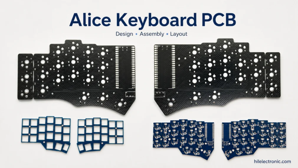
Alice Keyboard PCB Manufacturer | Custom Ergonomic Layout
An Alice keyboard PCB manufacturer must translate an...
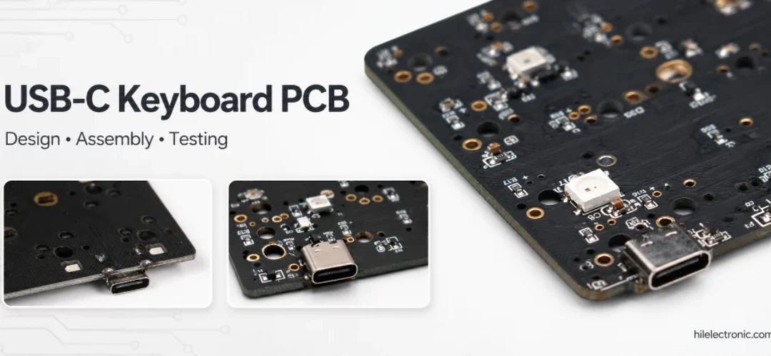
USB-C Keyboard PCB Manufacturer | ESD & Power Protection
A USB-C keyboard PCB manufacturer must control the...

Per-Key RGB Keyboard PCB Manufacturer & LED Assembly
A per-key RGB keyboard PCB manufacturer must control far...

Ortholinear Keyboard PCB Manufacturer | Custom Grid Layout
An ortholinear keyboard PCB manufacturer must preserve a...
How to get a quote for PCBs
Let‘s run DFM/DFA analysis for you and get back to you with a report. You can upload your files securely through our website. We require the following information in order to give you a quote:
-
- Gerber, ODB++, or .pcb, spec.
- BOM list if you require assembly
- Quantity
- Turn time
In addition to PCB manufacturing, we offer a comprehensive range of electronic services, including PCB design, PCBA, and turnkey solutions. Whether you need help with prototyping, design verification, component sourcing, or mass production, we provide end-to-end support to ensure your project’s success.
For PCBA services, please provide your BOM (Bill of Materials) and any specific assembly instructions. We also offer DFM/DFA analysis to optimize your designs for manufacturability and assembly, ensuring a smooth production process.