
A Guide to Circuit Board Stiffeners for Flexible and Rigid-Flex PCBs

Circuit board stiffeners are not an original part of a PCB; instead, they are additional components added to provide structural support and improve durability. Stiffeners are particularly vital for flexible PCBs, where specific areas of the board require added rigidity to prevent bending, flexing, or mechanical failure during manufacturing and use.
Discover the importance of circuit board stiffeners in flexible PCB design, their benefits, types, and placement tips to enhance durability and performance.
Advantages of Circuit Board Stiffeners
PCB stiffeners serve several purposes, making them indispensable for specific applications. Below are the primary benefits of incorporating stiffeners into PCB designs:
- Mechanical Support
Stiffeners increase the mechanical strength and rigidity of targeted PCB sections, reducing deformation and ensuring structural stability. This is especially important for heavy components or high-stress areas. - Flexural Resistance
They prevent bending and flexing in flexible PCBs, which protects copper traces and prevents damage during handling or repeated movement. - Enhanced Thermal Management
By aiding heat conduction and dissipation, stiffeners improve thermal management on the board, minimizing overheating risks. - Protection of Connection Points
Stiffeners provide reinforcement for connectors, sockets, and fragile components, ensuring they remain stable during insertion, removal, or use. - Support for Additional Components
Stiffeners create a sturdy base for components like heat sinks, sensors, or modules, enhancing the board’s overall functionality. - Precise Alignment During Assembly
They ensure proper alignment of the PCB during assembly, minimizing errors and improving efficiency. - Vibration and Resonance Mitigation
By reducing vibrations and resonance, stiffeners enhance signal integrity and reduce the risk of interference.
Types of Circuit Board Stiffeners
Circuit board stiffeners come in several types, each designed to address specific application requirements such as mechanical strength, flexibility, thermal resistance, or cost-effectiveness. Below, we break down the most commonly used stiffeners and their specific applications.
1. Polyimide (PI) Stiffeners
Polyimide stiffeners, such as Kapton, are lightweight, thermally stable, and highly flexible. They are widely used in areas like gold finger connectors or Zero Insertion Force (ZIF) connectors, where precise thickness and dynamic flexibility are essential. Polyimide stiffeners are valued for their ability to withstand high temperatures (up to 400°C), making them ideal for soldering and high-temperature processes. Their ability to maintain dimensional stability while remaining flexible makes them perfect for dynamic flex regions where bending and movement are necessary during installation and use.
2. FR-4 Stiffeners
FR-4 stiffeners, made of fiberglass-reinforced epoxy laminate, are known for their rigidity, mechanical strength, and cost-effectiveness. These stiffeners are commonly applied in connector pads, solder joints, and component mounting areas, providing a stable and robust base during both assembly and operation. FR-4 stiffeners are particularly beneficial in automated manufacturing processes like pick-and-place or reflow soldering, where maintaining a flat and rigid surface is critical. While FR-4 lacks the flexibility of polyimide, its affordability and strength make it a go-to solution for designs prioritizing structural support.
3. Stainless Steel or Aluminum Stiffeners
For high-stress environments, stainless steel or aluminum stiffeners offer unparalleled mechanical strength, durability, and corrosion resistance. These materials are often used in industrial machinery, automotive systems, and aerospace applications, where PCBs are exposed to extreme vibration, mechanical stress, and temperature fluctuations. Metal stiffeners also aid in thermal management, dissipating heat more effectively than non-metal alternatives, thereby enhancing the thermal performance of the PCB. Although they are heavier and more expensive, their superior mechanical properties make them indispensable for applications requiring extreme reliability.
4. Hybrid Stiffeners
Hybrid stiffeners combine materials like FR-4 and polyimide to create custom solutions for designs requiring varying levels of rigidity and flexibility. By integrating the strengths of both materials, hybrid stiffeners can address complex design challenges, such as balancing mechanical stability with flexibility or thermal resistance. These stiffeners are particularly suited for advanced applications like foldable devices, high-frequency circuits, or PCBs operating under diverse conditions. Hybrid solutions provide a tailored approach to achieving optimal durability and performance in specific sections of the circuit board.
Comparison of Circuit Board Stiffeners

If this requirement affects sourcing or production release, compare it with rigid-flex PCB manufacturing and PCB layout review before sending the final files for review.
Placement of Stiffeners in Flexible PCBs
Top Layer Stiffeners: Stiffeners on the top layer are commonly used to provide structural support to the PCB’s surface or specific areas. This placement is ideal for designs where the top layer must carry significant weight or accommodate components like LED displays. Top-layer stiffeners ensure even weight distribution, reduce deformation, and maintain the integrity of the PCB during assembly and operation. They are particularly effective in reinforcing solder joints and connectors located on the top side of the PCB.
Bottom Layer Stiffeners: Stiffeners on the bottom layer offer localized support to areas subjected to high mechanical stress or heavy components, such as connectors or solder points. This placement protects the PCB during soldering and mechanical assembly while preventing fatigue and damage over time. Bottom-layer stiffeners are especially useful in designs where specific regions need added rigidity without compromising the flexibility of the rest of the PCB.
Dual-Layer Stiffeners: Applying stiffeners to both the top and bottom layers provides maximum rigidity and structural integrity. This configuration is particularly effective for applications exposed to mechanical stress from multiple directions or harsh environments with high vibrations and extreme temperatures. Dual-layer stiffeners enhance the PCB’s ability to remain stable and functional under demanding conditions, such as in automotive and aerospace systems.
Multi-Layer Stiffener Designs: Multi-layer stiffeners are often used in flexible PCBs that experience continuous mechanical stress or operate under extreme environmental conditions. For instance, in automotive applications, dual-layer stiffeners help the PCB withstand vibration, compressive forces, and thermal cycling. This balanced reinforcement distributes mechanical stress evenly, ensuring the PCB’s reliability and extending its lifespan. Multi-layer stiffener designs are particularly valuable in high-performance and mission-critical systems.
How to Attach Stiffeners to Flexible PCBs
Attaching stiffeners to flexible PCBs is a common method to increase rigidity in specific areas, such as around connectors or mounting holes, to enhance mechanical strength and stability. Common stiffener materials include FR4 (fiberglass), polyimide, and metals like stainless steel. The process typically involves using adhesives, such as heat-activated adhesive (HAA) or pressure-sensitive adhesive (PSA), depending on the application requirements and materials involved.
The first step is to prepare the surface of the flexible PCB. Clean the surface thoroughly using isopropyl alcohol to remove dust, grease, and other contaminants. Inspect the area where the stiffener will be attached to ensure it is flat and free of defects. Then, prepare the stiffener by cutting it to the required shape and dimensions. Make sure the stiffener aligns precisely with key features of the PCB, such as connectors or mounting holes, to avoid any misalignment during installation.
Next, apply the adhesive and bond the stiffener to the PCB. For heat-activated adhesives, align the stiffener on the PCB and use a heat press or laminator to apply the appropriate temperature (e.g., 180°C), pressure, and duration (around 60 seconds). Allow it to cool before handling. For pressure-sensitive adhesives, align the stiffener carefully and apply uniform pressure using a roller or pressing tool to ensure a firm bond without air bubbles or gaps.
Finally, inspect the bonding quality and perform any necessary post-processing. Check the alignment and adhesive uniformity through visual inspection, and test the stiffener’s adhesion by applying light mechanical pressure. If needed, drill or punch holes for connectors or mounting, and trim any excess material to match the PCB profile. By following these steps, you can securely attach stiffeners to flexible PCBs, ensuring mechanical stability and extended durability.
Design Considerations for Circuit Board Stiffeners
When incorporating stiffeners into PCB designs, it is crucial to carefully evaluate various factors to ensure optimal functionality, mechanical stability, and manufacturability. Below are five key considerations to guide your design process.
1. Material Selection
The choice of stiffener material should align with the mechanical and thermal demands of the application. For high-temperature environments, polyimide (PI) is an excellent choice due to its superior thermal resistance and flexibility. For applications where cost-effective rigidity is a priority, FR-4 is commonly used. In scenarios requiring maximum mechanical strength, metal stiffeners (e.g., stainless steel) may be employed, although they add weight and complexity.
2. Placement Optimization
Stiffeners should only be applied where necessary to avoid unnecessary weight and cost. Typical areas for placement include:
-
- Connectors: To prevent flexing and mechanical strain during mating and unmating.
- Mounting points: To stabilize the PCB during installation. Avoid overusing stiffeners in non-critical areas to maintain the flexibility of the PCB where it is needed and reduce overall weight.
3. Dynamic Movement
In applications requiring bending or dynamic movement, it is essential to avoid placing stiffeners in areas of the PCB that must remain flexible. For instance, stiffeners should not be added to regions designed for flexing, as this can restrict movement and lead to stress points. Improper placement may cause fractures, delamination, or a decrease in the PCB’s reliability.
4. Thickness Control
The thickness of the stiffener should be carefully optimized to provide adequate mechanical support without creating assembly or weight issues. Thicker stiffeners are better for high-stress areas but may interfere with component placement or increase the overall PCB height. Thinner stiffeners are suitable for space-constrained assemblies but should still meet the required mechanical support specifications.
5. Thermal Expansion Compatibility
A critical aspect of stiffener design is ensuring that the coefficient of thermal expansion (CTE) of the stiffener material matches that of the PCB. A mismatch in CTE can cause warping during temperature changes or delamination of the adhesive layer. Selecting materials with compatible CTE values ensures the long-term durability and reliability of the PCB, especially in environments with fluctuating temperatures.
By carefully addressing these five considerations—material selection, placement optimization, dynamic movement, thickness control, and thermal expansion compatibility—you can design PCBs with stiffeners that provide the required support while maintaining flexibility, reliability, and ease of assembly.
Conclusion
Circuit board stiffeners play a critical role in improving the durability, thermal management, and mechanical stability of PCBs, particularly flexible designs. By selecting the appropriate stiffener type, material, and placement method, engineers can address specific challenges and optimize the performance of their designs.
As the demand for lightweight and reliable electronic devices continues to grow, the proper use of circuit board stiffeners will remain a key factor in ensuring the success of advanced PCB designs.
Get a Free PCB & PCBA Quote

Recommended Posts
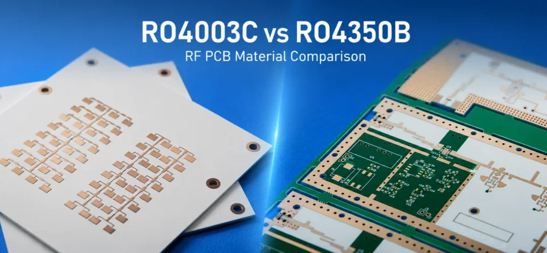
RO4003C vs RO4350B: Rogers Datasheet Values, LoPro Foil, and Stackup Choices
Figure 1. RO4003C vs RO4350B selection depends on...

PCB Copper Plating: Process, Thickness, Quality Control
Figure 1. PCB copper plating process for hole-wall and...

Taconic RF-35 PCB Manufacturing Service — Prototype Through Volume Production
Figure 1. Taconic RF-35 PCBTaconic RF-35 is the workhorse...

Isola Astra MT77 PCB Manufacturing
Figure 1. Isola Astra MT77 PCB ManufacturingIsola Astra...
How to get a quote for PCBs
Let us run DFM/DFA analysis for you and get back to you with a report.
You can upload your files securely through our website.
We require the following information in order to give you a quote:
-
- Gerber, ODB++, or .pcb, spec.
- BOM list if you require assembly
- Quantity
- Turn time
In addition to PCB manufacturing, we offer a comprehensive range of electronic services, including PCB design, PCBA (Printed Circuit Board Assembly), and turnkey solutions. Whether you need help with prototyping, design verification, component sourcing, or mass production, we provide end-to-end support to ensure your project’s success. For PCBA services, please provide your BOM (Bill of Materials) and any specific assembly instructions. We also offer DFM/DFA analysis to optimize your designs for manufacturability and assembly, ensuring a smooth production process.