
PLC PCB Manufacturer for Fabrication and Assembly Services

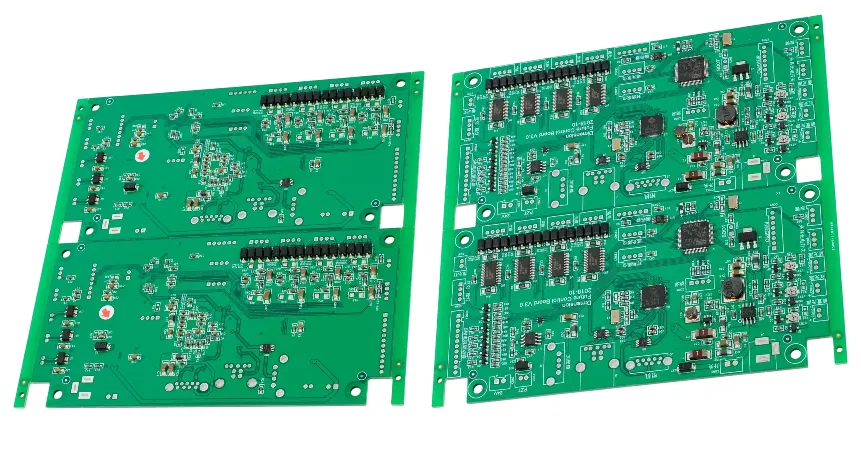
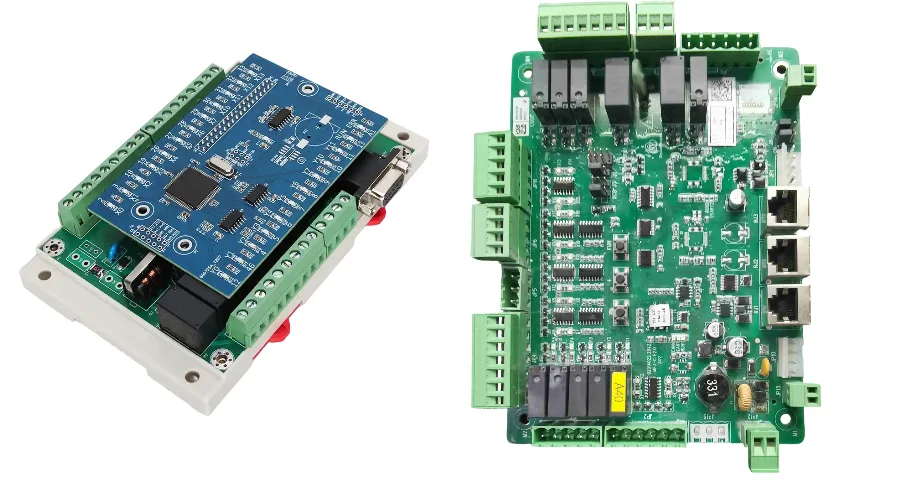
PLC PCBs fail differently than consumer electronics PCBs, and they fail in ways that matter more. A smartphone display flicker is an inconvenience. A failed PLC board in an automotive assembly line stops production at a cost that can reach tens of thousands of dollars per hour. The gap between a circuit board manufacturer that understands this and one that doesn’t shows up in decisions made before a single panel is run — in how the stack-up handles EMI, in how via structures are reinforced against vibration, in whether the soldermask chemistry holds up at 85°C ambient, in whether the board passes IPC Class 3 inspection or just Class 2. Highleap Electronics is a PLC PCB manufacturer and PCBA factory based in China with dedicated production lines and engineering processes built around the reliability requirements of industrial control boards, including PLC mainboards, I/O expansion modules, communication interface cards, and power supply boards.
Highleap’s PLC PCB Manufacturing Capabilities at a Glance
- IPC Class 2 & Class 3 Production: Selectable inspection standard per order; Class 3 for safety-critical and high-reliability PLC applications.
- Industrial Stack-Up Support: 2–20 layer FR-4, high-Tg FR-4 (Tg 150/170°C), PTFE/Rogers for communication interface cards, heavy copper (2–6 oz) for power modules.
- EMI/EMC Manufacturing Controls: Controlled-impedance fabrication, measured verification, and copper pour strategies verified against your EMC design intent.
- Environmental Resistance: Conformal coating (acrylic, silicone, polyurethane), potting services, and surface finishes rated for industrial temperature and humidity ranges.
- Long-Term Supply Commitment: Industrial customers need predictable supply over 5–10 year product lifecycles. We maintain tooling and production records for active industrial accounts.
Request a PLC PCB Manufacturing Quote
Table of Contents
- Why PLC PCB Manufacturing Is Not Standard PCB Manufacturing
- IPC Class 2 vs. Class 3: What Standard Does Your PLC Board Actually Need?
- Stack-Up Materials and Layer Count for Industrial Control Boards
- EMI/EMC Manufacturing Controls That Matter for PLC Applications
- Thermal and Environmental Durability in PLC PCB Production
- Long-Term Supply: Why Industrial PCB Manufacturers Think in Decades
- Frequently Asked Questions
Why PLC PCB Manufacturing Is Not Standard PCB Manufacturing
The phrase “industrial-grade PCB” gets applied loosely in marketing materials. Understanding what it actually requires in production separates manufacturers who can deliver it from those who are simply labeling standard-process boards with industrial language.
PLC circuit boards operate in environments that consumer and commercial electronics never see: ambient temperatures that swing from -10°C to 70°C within a single operational cycle, continuous mechanical vibration from nearby motors and actuators, power rail transients from inductive loads switching in the same cabinet, and the expectation of continuous unattended operation for years rather than months. These conditions impose requirements on the manufacturing process at every level — from laminate selection through surface finish choice through solder joint geometry through final inspection standard.
The most concrete difference is the failure tolerance. A consumer product with a 1% field failure rate is considered acceptable. For an industrial PLC that controls a manufacturing process, a 0.1% failure rate may still be unacceptable if the cost of each downtime event is high enough. Manufacturers who work primarily on consumer electronics may not have the process controls to achieve and verify the lower failure rates that industrial applications require.
Our engineering team reviews PLC PCB designs against an industrial-specific DFM checklist that covers via aspect ratio for through-hole reliability under vibration, copper weight adequacy for sustained current in power distribution traces, pad-to-trace clearance for high-voltage isolation between I/O circuits and logic circuits, and surface finish compatibility with the operating temperature range. These are not checks that appear on a standard consumer PCB DFM template.
IPC Class 2 vs. Class 3: What Standard Does Your PLC Board Actually Need?
IPC-A-610 and IPC-6012 define three product classes with increasing inspection stringency. The class you specify determines how your boards are inspected, what defect acceptance criteria apply, and ultimately what yield and cost you should expect.
| Characteristic | Class 1 | Class 2 | Class 3 |
|---|---|---|---|
| Target application | Consumer, general use | Industrial, commercial electronics | Safety-critical, high-reliability industrial |
| Downtime tolerance | Acceptable | Undesirable but tolerable | Not acceptable |
| Solder joint inspection | Basic visual | AOI + sampling | 100% AOI + X-ray on BGA/QFN |
| Conductor spacing criteria | Relaxed | Moderate | Tightest; no marginal conditions accepted |
| Via fill and barrel inspection | Visual only | Microsection sampling | Microsection required; barrel fill minimum 75% |
| Typical PLC application | Not recommended | General industrial automation, HVAC control | Machine safety, process control, medical-adjacent |
Most standard industrial PLC applications fall into Class 2. The inspection criteria are meaningfully more stringent than Class 1 consumer production without incurring the cost premium of Class 3, which is reserved for applications where an undetected defect creates safety or mission-critical risk. However, some PLC applications do warrant Class 3 — safety PLC boards (SIL 2/3 certified systems), boards in harsh environments where field service is difficult or expensive, and boards in applications where service life exceeds ten years.
We produce to both Class 2 and Class 3 at client specification. The class designation is confirmed during order review and documented in the production traveler. Inspection records are retained and available as part of the delivery package. For clients who are unsure which class their application requires, our engineering team can review the application context and provide a recommendation with the rationale documented.
Stack-Up Materials and Layer Count for Industrial Control Boards
Material selection for a PLC PCB is not a cosmetic decision. The laminate, copper weight, and layer configuration directly determine how the board performs under the thermal cycling, vibration, and electrical stress conditions of industrial installation.
FR-4 Tg and Why It Matters for PLC Applications
Standard FR-4 has a glass transition temperature (Tg) in the 130–140°C range. Above Tg, the laminate softens and dimensional stability degrades. In a PLC installed near a motor drive or mounted in a cabinet with limited airflow, the PCB surface temperature under load can easily approach 80–100°C ambient plus self-heating. Standard Tg FR-4 has inadequate thermal margin for this environment. We use high-Tg FR-4 (Tg 150°C or Tg 170°C) as the default for PLC applications. The cost premium over standard FR-4 is modest; the reliability improvement in thermal cycling environments is significant.
Heavy Copper for Power Distribution Layers
PLC power supply boards and I/O modules with high channel counts carry sustained current loads that standard 1 oz copper traces cannot handle without excessive temperature rise. We produce heavy copper circuit boards up to 6 oz for power distribution layers, with the ability to specify different copper weights on different layers within the same stack-up. Power layers at 3–4 oz, signal layers at 1 oz, is a common PLC power board configuration that we produce routinely.
High-Frequency Laminates for Communication Cards
PLC communication interface cards — particularly those carrying PROFIBUS, Industrial Ethernet (PROFINET, EtherCAT), or proprietary high-speed fieldbuses — require controlled-impedance traces with stable dielectric characteristics across temperature. Standard FR-4’s dielectric constant (Dk) varies meaningfully with temperature and frequency, which introduces phase error in high-speed differential pairs. For communication cards with data rates above 100 Mbps or RF-frequency interfaces, we work with PTFE-based or ceramic-filled laminates that provide stable Dk across the operating temperature range. Our high-frequency PCB fabrication process covers these material types with the same controlled-impedance verification we apply to RF and microwave boards.
Layer Count and Shielding Layer Strategy
PLC PCBs commonly run from 4 to 12 layers. The layer allocation matters for EMC performance: placing ground planes adjacent to high-speed signal layers, using dedicated power planes rather than polygon pours, and ensuring that analog I/O signal layers are not adjacent to switching power layers are all stack-up decisions that affect EMC behavior before the first component is placed. We review layer stack-up for PLC designs against these EMC-relevant criteria during DFM.
EMI/EMC Manufacturing Controls That Matter for PLC Applications
EMC performance is partly a design problem and partly a manufacturing problem. A design that meets EMC requirements in simulation can still fail radiated emissions testing if manufacturing introduces uncontrolled impedance discontinuities, pad geometry variations, or via stub resonances. As a PLC PCB manufacturer, our responsibility is to produce the board to the design’s intent — not to introduce manufacturing variability that alters the EMC behavior the designer calculated.
Controlled Impedance Fabrication and Verification
High-speed signal lines on PLC communication cards — differential pairs for Ethernet, RS-485, or CAN bus — are designed to specific impedance targets (typically 100Ω differential for Ethernet, 120Ω for CAN). Impedance is set by the trace width, trace spacing, dielectric thickness, and copper weight. All of these have manufacturing tolerance. We fabricate controlled-impedance boards with coupon-based impedance measurement on every production panel. The measurement results are included in the shipping documentation. Boards that fall outside the specified tolerance are rejected before shipment. Our controlled-impedance manufacturing process applies the same verification standard to PLC communication boards as to RF and high-speed data boards.
Via Stub Management
In multilayer PLC boards with through-hole vias, the unused via barrel below the signal layer forms a stub that resonates at frequencies that degrade signal integrity. For PLC communication boards with data rates above 1 Gbps, back-drilling (removing the stub portion of the via after drilling) is required. We perform back-drilling with controlled depth tolerance and verify stub length against the design specification.
Copper Pour and Stitching Via Practices
Ground plane continuity and via stitching around high-frequency circuit areas, shielded connectors, and board edge boundaries affect radiated emission behavior. We follow your copper pour and stitching via specification during layout review and flag cases where copper pour breaks or stitching via spacing may create ground plane impedance discontinuities that could affect EMC compliance.
Thermal and Environmental Durability in PLC PCB Production
The operating environment of an industrial PLC is hostile to electronics in ways that the manufacturing process must account for directly. Temperature, humidity, vibration, and chemical exposure are all factors that determine how long a PLC board remains functional in service.
Conformal Coating
Conformal coating protects assembled PLC boards from moisture, condensation, industrial chemicals, and surface contamination. We apply acrylic, polyurethane, silicone, and epoxy conformal coatings depending on the application requirements. Acrylic is the most common choice for general industrial applications — it provides good moisture and chemical resistance and is easily repaired in the field. Silicone is specified for applications with continuous exposure to temperatures above 130°C or to aggressive solvents. Polyurethane provides superior abrasion resistance for boards in mechanically abrasive environments. Coating is applied by selective spray or dip process, with defined masking to keep connectors, test points, and adjustment potentiometers uncoated.
Surface Finish Compatibility with Industrial Temperature Ranges
ENIG (Electroless Nickel Immersion Gold) is the preferred surface finish for PLC boards for reasons beyond pad flatness. The nickel barrier layer provides stable solderability across the temperature cycling that PLC boards experience both during reflow and in service. HASL presents oxidation and solderability consistency problems in boards stored before assembly or used in high-humidity environments. For long-lead-time industrial projects where bare boards may be stored for months before assembly, ENIG’s shelf life advantage is particularly relevant. Our surface finish selection guidance covers the industrial application trade-offs in detail.
Thermal Shock and Cycling Reliability
PLC boards in outdoor or transportation-adjacent applications may experience rapid thermal cycling — cold startup in winter conditions followed by operation at rated power. Via barrel cracking under repeated thermal cycling is a known failure mode in through-hole vias in multilayer boards. Via barrel reliability is governed by the copper deposit thickness in the barrel, the aspect ratio of the via, and the CTE mismatch between the copper and the laminate. We specify via copper thickness to IPC-6012 Class 3 minimums for PLC applications with significant thermal cycling exposure, regardless of the overall inspection class specified for the build.
Long-Term Supply: Why Industrial PCB Manufacturers Think in Decades
Industrial automation equipment has product lifecycles that are fundamentally different from consumer electronics. A PLC installed in a manufacturing facility in 2025 may still be in active service in 2035, requiring replacement boards for maintenance. The manufacturer who built those boards needs to be capable of reproducing them — or at minimum of providing technically compatible alternatives — a decade after the original order.
This longevity requirement affects how we manage industrial PCB accounts differently from consumer or commercial accounts.
Production tooling — Gerber files, drill files, panel layout, impedance coupon design — is archived and retained for active industrial accounts. We do not purge production records after a defined period the way some factories do. When a reorder comes in for a PLC board that was last produced three years ago, we pull the original production package and verify it against any component or material changes that have occurred in the intervening period before running.
Component lifecycle management is particularly important for PLC boards. Specific MCUs, communication controllers, or analog I/O front-end ICs may reach end-of-life status during the service life of the equipment they are installed in. We track EOL announcements from major component manufacturers against the BOMs of active industrial accounts and notify clients when a BOM component approaches EOL — giving them the opportunity to assess alternatives or place a last-time-buy order before the part becomes unavailable.
For industrial customers with particularly long lifecycle requirements, we also provide last-time-buy manufacturing services: a defined production run at the time of EOL notice, designed to provide enough boards to cover the remaining service life of the equipment in the field. This is a normal service model for industrial electronics supply chains and one we accommodate as a standard account service.
Frequently Asked Questions
What is the difference between a PLC PCB and a standard industrial PCB?
PLC PCBs specifically serve the function of programmable logic controller hardware — CPU boards, I/O expansion modules, communication cards, and power supply boards within a PLC system. They share the general reliability requirements of industrial electronics but add PLC-specific requirements: isolated I/O circuit structures, industrial communication protocol routing (PROFIBUS, EtherCAT, CAN), and the backplane connector interfaces that allow modules to communicate within a rack system.
Do you produce PLC PCBs to IPC Class 3?
Yes. We produce to IPC-A-610 Class 3 and IPC-6012 Class 3 at client specification. Class 3 production requires additional inspection steps, microsection verification, and tighter acceptance criteria that we document in the production traveler and delivery package.
Can you handle PLC PCBs with isolated I/O circuits requiring high-voltage creepage and clearance?
Yes. Industrial I/O boards frequently require isolation barriers rated to 1500V or higher between field-side connections and logic-side circuits. We review your creepage and clearance requirements against IEC 60664-1 or your specific isolation standard during DFM and verify that the board layout meets the specified isolation distance with appropriate manufacturing process margins.
What is your lead time for PLC PCB manufacturing?
Bare board fabrication for standard 4–8 layer PLC PCBs typically runs 7–12 working days. Turnkey PCBA with standard component availability runs 15–20 working days. Boards requiring specialized laminates (high-Tg FR-4, PTFE) or heavy copper processing may require additional fabrication time. We confirm lead time during the DFM review stage.
Do you provide manufacturing documentation suitable for industrial quality audits?
Yes. Our standard industrial delivery package includes fabrication certificates, IPC inspection reports, material certificates (UL-rated laminate, RoHS compliance), AOI reports, controlled-impedance test data (where applicable), and test records. Additional documentation — PPAP, FMEA support, or customer-specific quality forms — can be arranged for accounts with formal supplier qualification requirements.

Recommended Posts

Custom Rogers RO4835 PCB Fabrication & Assembly Services
Figure 1. Rogers RO4835 PCBRogers RO4835 PCB is a...

Nelco N4000-13 PCB Material and Manufacturing Guide | Highleap Electronics
Figure 1. Nelco N4000-13 PCBNelco N4000-13 PCB is a...

Rogers RT/duroid 6002 PCB Manufacturer — Specifications, Stackup, Quote
Figure 1. Rogers RT/duroid 6002Rogers RT/duroid 6002 is...

Miniaturize Antennas with Rogers TMM Laminates
Figure 1. Rogers TMM Executive Summary: Rogers TMM...
How to get a quote for PCBs
Let us run DFM/DFA analysis for you and get back to you with a report.
You can upload your files securely through our website.
We require the following information in order to give you a quote:
-
- Gerber, ODB++, or .pcb, spec.
- BOM list if you require assembly
- Quantity
- Turn time