
Rigid-Flex PCB Stackup: Common Structures, Materials, and Signal Strategies

Modern electronic systems often require interconnect solutions that deliver both the stability of rigid boards and the adaptability of flexible circuits. Rigid-flex PCB stackup design plays a central role in achieving this balance, as the arrangement of rigid and flex layers, material selection, and structural choices directly influence signal integrity, mechanical reliability, and manufacturability.
In this article, we will explore the common rigid-flex PCBs stackup structures, material strategies, and signal/power distribution considerations that guide engineers in developing reliable, cost-effective designs for advanced applications.
Common Rigid-Flex PCB Stackup Configurations
1. Single-Layer Flex with Rigid Sections
This basic rigid-flex PCB stackup configuration uses a single conductive layer in the flex region, typically polyimide with copper foil. It minimizes bend stress while maintaining reliable interconnection between rigid sections.
Typical Structure:
- Rigid sections: 4–8 layers with FR4 core
- Flex section: single copper layer on polyimide
- Coverlay for protection of flex conductors
Best suited for simple interconnections in consumer displays and sensors, this stackup offers excellent bendability while rigid areas handle routing and component mounting.
2. Double-Layer Flex with Multilayer Rigid Sections
A more advanced rigid-flex PCB stackup design adds a second flex layer to increase routing density while retaining flexibility. Rigid sections often reach 6–12 layers to support complex circuits.
Design Considerations:
- Symmetric copper distribution reduces flex curl
- Continuous ground plane ensures signal integrity
- Avoid vias in high-stress bend zones
- Matched layer thickness prevents delamination
Commonly applied in medical monitoring devices and automotive control modules, this configuration balances density and flexibility.
3. Multilayer Flex Interleaved with Rigid Sections
The most complex rigid-flex PCB stackup supports multiple flexible layers for power distribution, differential signaling, and EMI shielding. These advanced stackup configurations require precise material control and optimized design.
Critical Design Elements:
- Adhesive choice affects flexibility and temperature resistance
- Optimized copper thickness balances conductivity and bendability
- Symmetric layer design prevents warpage
- Transition zones engineered to minimize impedance discontinuities
Typical in aerospace and satellite systems, this stackup enables high-density, three-dimensional packaging—often considered the best rigid-flex PCB stackup for high speed design and harsh environments.
Material Selection and Layer Composition
1. Rigid Section Materials
The rigid portions of rigid-flex PCB stackup typically employ FR4 materials for cost-effectiveness and proven reliability. High-performance applications within a rigid-flex PCB stackup may specify low-loss materials such as Rogers or Isola products for improved electrical characteristics.
Material Selection Criteria:
- Standard FR4 provides adequate performance for most rigid-flex PCB stackup applications up to 1 GHz
- High-Tg FR4 improves thermal reliability in elevated temperature environments within a rigid-flex PCB stackup
- Low-loss materials become necessary for frequencies above 1 GHz in high-speed rigid-flex PCB stackup designs
- Coefficient of thermal expansion matching prevents assembly stress in the rigid-flex PCB stackup
2. Flexible Section Materials
Polyimide substrates dominate flexible section material selection in a rigid-flex PCB stackup due to excellent flexibility, temperature stability, and chemical resistance. The FR4 + polyimide combination creates material property transitions that require careful design consideration in rigid-flex PCB stackup layouts.
Polyimide Characteristics:
- Superior flexibility enables tight bend radii in the flexible section of rigid-flex PCB stackup without conductor fracture
- High temperature stability supports lead-free soldering processes in rigid-flex PCB stackup assembly
- Chemical resistance provides reliability in harsh environments for rigid-flex PCB stackup applications
- Lower dielectric constant compared to FR4 affects impedance calculations in rigid-flex PCB stackup design
Adhesive selection significantly impacts flexibility and reliability in rigid-flex PCB stackup designs. Adhesive-less construction using thermally bonded polyimide provides superior flexibility but requires precise processing control.
3. Copper Foil Considerations
Copper foil selection directly affects flexible section performance and reliability in rigid-flex PCB stackup. Rolled annealed copper provides superior flexibility compared to electrodeposited copper, making it the preferred choice for dynamic flex applications within a rigid-flex PCB stackup.
Copper Foil Properties:
- Rolled annealed copper maintains ductility under repeated bending in rigid-flex PCB stackup
- Electrodeposited copper offers better surface smoothness for fine-pitch applications in rigid-flex PCB stackup
- Copper thickness optimization balances conductivity requirements with flexibility in rigid-flex PCB stackup
- Surface treatment affects adhesion and solderability characteristics in rigid-flex PCB stackup

Rigid-Flex PCB
Rigid-Flex PCB Stackup Signal and Power Layer Strategies
1. High-Speed Signal Integrity Optimization
Signal integrity in rigid flex PCB designs requires careful consideration of impedance transitions between rigid and flexible sections. The dielectric constant differences between FR4 and polyimide materials create impedance discontinuities that must be managed through controlled geometry adjustments.
Impedance Control Techniques:
- Trace width compensation in flexible regions accounts for polyimide dielectric properties
- Ground plane continuity maintains consistent return path impedance
- Differential pair routing requires matched propagation delays across material transitions
- Via stub elimination prevents high-frequency resonances
The best rigid-flex PCB stackup for high speed design incorporates low-loss materials in signal-critical layers, maintains symmetric stripline configurations where possible, and minimizes the number of layer transitions in high-frequency signal paths. Edge-coupled differential pairs perform better than broadside-coupled configurations in flexible regions due to reduced crosstalk from bend-induced geometry variations.
2. Power Distribution Network Design
Effective power distribution in rigid-flex stackups demands strategic placement of power and ground planes to maintain low impedance paths while accommodating mechanical flexibility requirements. The rigid flex PCB power distribution strategy must address both electrical performance and mechanical reliability.
Power Plane Implementation:
- Rigid sections utilize solid power and ground planes for minimum impedance
- Flexible sections employ power traces or mesh patterns to maintain conductivity during bending
- Decoupling capacitor placement concentrates near rigid-flex transition zones
- Power supply filtering integrates into rigid sections for optimal performance
Voltage regulation circuits position in rigid sections to minimize noise coupling into flexible interconnections. Multi-rail power systems require careful routing to prevent cross-regulation issues when flexible sections carry multiple supply voltages.
3. EMI Shielding and Crosstalk Mitigation
Electromagnetic compatibility considerations become complex in rigid-flex designs due to the mixed dielectric environment and potential for coupling between rigid and flexible sections. Proper layer allocation and shielding strategies prevent interference issues.
Shielding Strategies:
- Ground planes in rigid sections provide comprehensive shielding
- Flexible sections utilize hatched ground patterns or dedicated shield layers
- Critical signals route between ground references to minimize crosstalk
- Flex section twisting or controlled orientation reduces radiated emissions
Rigid-Flex PCB Stackup Design Considerations
1. Transition Zone Optimization
The rigid-to-flexible transition zones represent critical stress concentration areas requiring careful geometric design. Rigid-flex PCB design guidelines emphasize gradual stiffness transitions and stress relief features to prevent premature failure.
Transition Design Elements:
- Tapered stiffener edges distribute stress over larger areas
- Tear-drop via connections prevent stress concentration at via intersections
- Copper pour extensions provide mechanical reinforcement
- Layer termination staging prevents abrupt stiffness changes
2. Bend Radius and Mechanical Constraints
Flexible section bend radius limitations depend on stackup thickness, copper coverage, and dynamic versus static bending requirements. Single-layer flex circuits typically accommodate bend radii of 6-10 times the total thickness, while multilayer constructions require larger radii.
Bend Radius Guidelines:
- Static applications: 6-10× total stackup thickness
- Dynamic applications: 20-50× total stackup thickness
- Copper coverage percentage affects minimum bend radius
- Layer count increases minimum allowable bend radius
3. Stiffener Integration and Mechanical Support
Mechanical support elements including PCB stiffeners provide local rigidity enhancement in flexible regions where component mounting or connector attachment occurs. Stiffener selection and placement significantly impact overall assembly reliability and performance.
Process Considerations:
- Lamination cycle optimization prevents delamination and ensures adhesion
- Drilling parameters adjust for material stack variations
- Routing accuracy requirements increase due to flexible section tolerances
- Testing methodologies must address both rigid and flexible section requirements
Designers must collaborate closely with manufacturing teams to ensure stackup designs remain within process capabilities. Early design reviews identify potential manufacturing challenges and optimize designs for yield and cost-effectiveness.
Conclusion
Rigid-flex PCB stackup design represents the intersection of electrical, mechanical, and materials engineering. The right stackup configuration is essential to balancing signal integrity, mechanical reliability, manufacturability, and cost-effectiveness across demanding applications from consumer electronics to aerospace systems.
Highleap Electronics Stackup Design Capabilities:
- Layer counts from 2–20 in rigid sections with 1–6 flexible layers
- Expertise in FR4, high-Tg, and low-loss specialty materials
- Advanced via options including blind, buried, and microvias
- Design for manufacturing (DFM) analysis to optimize yield and cost
- Environmental testing validation for long-term reliability
- Fast turn rigid-flex PCB prototyping to accelerate development
At Highleap Electronics, our engineering team collaborates with customers from concept through production, delivering stackup solutions that ensure electrical performance, mechanical durability, and efficient manufacturing. If you are seeking a trusted partner for reliable and cost-effective rigid-flex PCB manufacturing, contact us today to discuss your project needs.

Recommended Posts
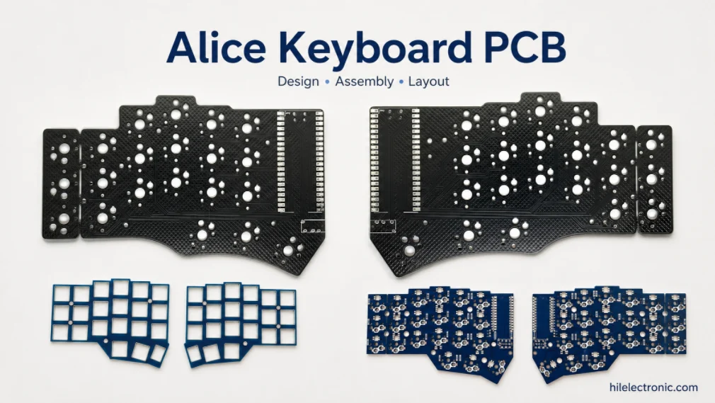
Alice Keyboard PCB Manufacturer | Custom Ergonomic Layout
An Alice keyboard PCB manufacturer must translate an...
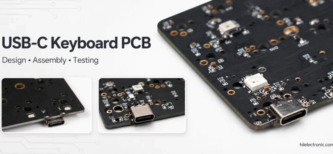
USB-C Keyboard PCB Manufacturer | ESD & Power Protection
A USB-C keyboard PCB manufacturer must control the...

Per-Key RGB Keyboard PCB Manufacturer & LED Assembly
A per-key RGB keyboard PCB manufacturer must control far...

Ortholinear Keyboard PCB Manufacturer | Custom Grid Layout
An ortholinear keyboard PCB manufacturer must preserve a...
How to get a quote for PCBs
Let‘s run DFM/DFA analysis for you and get back to you with a report. You can upload your files securely through our website. We require the following information in order to give you a quote:
-
- Gerber, ODB++, or .pcb, spec.
- BOM list if you require assembly
- Quantity
- Turn time
In addition to PCB manufacturing, we offer a comprehensive range of electronic services, including PCB design, PCBA, and turnkey solutions. Whether you need help with prototyping, design verification, component sourcing, or mass production, we provide end-to-end support to ensure your project’s success.
For PCBA services, please provide your BOM (Bill of Materials) and any specific assembly instructions. We also offer DFM/DFA analysis to optimize your designs for manufacturability and assembly, ensuring a smooth production process.