
Rogers TMM10i PCB Fabrication: Solving DFM Challenges

When RF engineers need to drastically shrink the footprint of a patch antenna, power amplifier, or cavity filter, they require a substrate with a dielectric constant (Dk) approaching 10. While brittle alumina ceramic was traditionally used for this, Rogers TMM10i provides a highly viable alternative: a thermoset hydrocarbon resin heavily loaded with ceramic that delivers an isotropic Dk of 9.80 while retaining the flat form factor of a printed circuit board.
However, while designing a TMM10i thermoset microwave board in simulation software is straightforward, physically manufacturing it is notoriously difficult. Because the material is exceptionally dense and abrasive, standard board houses often destroy their CNC tooling and scrap panels on the very first run. Successfully producing a custom Rogers TMM10i microwave PCB requires a manufacturing partner who intimately understands the mechanical limits of high-ceramic laminates.
Executive Summary: TMM10i Material & Processing
- Dielectric Constant (Dk): 9.80 ± 0.245 (Perfectly isotropic in X, Y, and Z axes).
- Thermal Coefficient of Dk (TCDk): -43 ppm/°C (Highly stable phase response over temperature).
- Primary Fabrication Challenge: Extreme tool wear and via micro-cracking caused by dense ceramic fillers.
- Metallization Advantage: Does not require hazardous sodium etching or plasma desmear (unlike PTFE-based laminates).
Table of Contents
Why Choose Rogers TMM10i for Dk 9.80 Microwave Designs?
Most high-frequency laminates, including standard FR-4 and many PTFE materials, rely on woven fiberglass for structural support. This creates an anisotropic effect—meaning the dielectric constant differs slightly depending on whether the RF signal travels along the X, Y, or Z axis.
TMM10i is uniquely formulated without woven glass. This makes the material perfectly isotropic. For engineers designing intricate 3D waveguide structures, the Dk remains exactly 9.80 in all three dimensions. This guarantees that your HFSS or CST software simulations will translate flawlessly into the physical board. Additionally, its Coefficient of Thermal Expansion (CTE) is exceptionally close to copper, preventing plated through-hole (PTH) failures during extreme thermal cycling in aerospace environments.
Manufacturing Challenges of TMM10i: Drill Wear and Micro-Cracking
To achieve a Dk of 9.80, Rogers heavily loads the hydrocarbon resin with silica and ceramic particles. The resulting panel behaves less like a plastic PCB and more like a fragile ceramic plate. This is the absolute core bottleneck of TMM10i RF board fabrication. If a factory applies standard machining parameters to this material, the yield rate will plummet.
The Root Cause of Via Failure: Micro-Cracking
The ceramic filler in TMM10i acts like microscopic sandpaper against CNC drill bits. When drilling a standard FR-4 panel, a tungsten carbide drill bit might last for 2,000 holes before dulling. On TMM10i, the cutting edge of that exact same bit is destroyed in under 100 holes.
If a manufacturer tries to push a dull drill bit through this brittle substrate to save money, it will not cut the resin cleanly. Instead, it will punch and tear its way through. This blunt force causes severe micro-cracking along the via hole wall.
These invisible, microscopic fractures act as sponges, trapping plating chemicals during the wet process. When the board later goes through the SMT reflow oven, those trapped liquid chemicals boil, outgas rapidly, and literally blow the copper plating off the via wall. This results in immediate, unrepairable open-circuit failures.
The Highleap Engineering Solution
To prevent these failures, an expert Rogers TMM10i ceramic PCB factory must implement strict CAM (Computer-Aided Manufacturing) rules:
- Capped Hit Counts: We enforce extremely strict drill bit replacement schedules, discarding bits at a fraction of their normal lifespan to guarantee a sharp cut.
- Reduced Spindle Speeds: We drastically reduce the Z-axis plunge rate (chip load) and spindle RPM to prevent frictional heat from inducing thermal stress fractures in the dielectric.
- Diamond-Cut Routing: Standard fluted router bits will tear the ceramic particles out, leaving jagged board edges. We utilize specialized diamond-cut router bits running at customized, ultra-slow feed rates to ensure perfectly smooth profiles.
Understanding Your Rogers TMM10i PCB Fabrication Cost
Procurement teams and hardware engineers often wonder why high-ceramic laminates carry a premium manufacturing price tag. The raw material is only part of the equation. The true driver behind your Rogers TMM10i PCB fabrication cost is the exponential tool wear (consuming dozens of drill and router bits per panel) and the incredibly slow CNC machining times required to treat the material with the necessary delicacy.
However, TMM10i provides a massive chemical processing advantage that offsets some of this expense. Unlike high-Dk PTFE materials (such as RO3010), TMM10i is a hydrocarbon thermoset. It does not require hazardous sodium etching or expensive vacuum plasma desmear prior to metallization. A capable China Rogers TMM10i PCB manufacturer can process these boards through standard electroless copper lines, significantly reducing lead times compared to Teflon-based alternatives.
Sourcing Reliable Fabrication and PCBA for Ceramic-Filled Boards
In the microwave industry, hardware validation must happen fast. While we provide quick turn Rogers TMM10i PCB prototyping, we strongly advise against having your bare boards fabricated at one facility and shipped to another third-party vendor for assembly. TMM10i is incredibly brittle; moving it between multiple suppliers drastically increases the risk of edge chipping and handling contamination.
To eliminate this risk, Highleap Electronics operates as a single-source Rogers TMM10i high dk PCB supplier. We transition your project seamlessly from our specialized high-frequency PCB manufacturing lines directly into our turnkey PCB assembly facilities.
As your dedicated Rogers TMM10i circuit board maker, we utilize Laser Direct Imaging (LDI) to hold trace impedance perfectly steady at Dk 9.80, and we deploy 3D X-Ray (AXI) inspection to guarantee void-free thermal grounding beneath high-power RF components. This ensures your final product performs exactly as intended.

Recommended Posts

Rogers TMM6 PCB Manufacturing for Microwave Filters
Table of contentsWhy Microwave Filter Designers Use...

Taconic fastRise 27 Prepreg PCB Bonding and HDI Fabrication Service
Table of contentsWhat fastRise 27 Is—and What You Are...
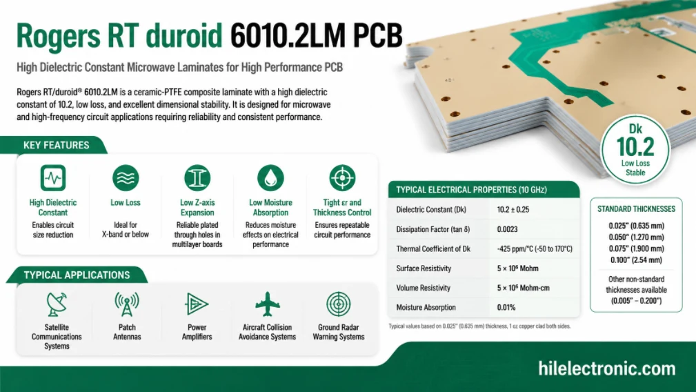
Rogers RT/duroid 6010.2LM PCB Manufacturer and Fabrication Service
Table of contentsIs RT/duroid 6010.2LM the Right Material...
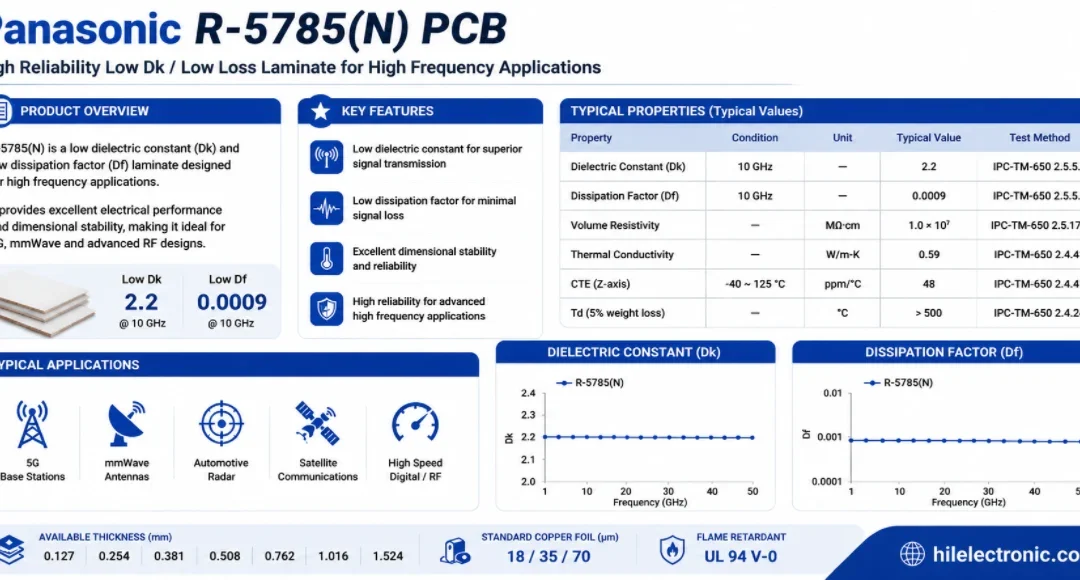
Panasonic R-5785(N) MEGTRON 7 PCB Manufacturer and Fabrication
Table of contentsWhen a Design Should Move to R-5785(N) /...
How to get a quote for PCBs
Let us run DFM/DFA analysis for you and get back to you with a report.
You can upload your files securely through our website.
We require the following information in order to give you a quote:
-
- Gerber, ODB++, or .pcb, spec.
- BOM list if you require assembly
- Quantity
- Turn time