
Rogers High-Dk PCB Fabrication & Turnkey Assembly

As 5G telecommunications, aerospace telemetry, and 77GHz automotive radar systems demand increasingly aggressive circuit miniaturization, hardware engineers are forced to utilize substrates with higher Dielectric Constants (Dk). In RF engineering, the physical size of a resonant circuit is inversely proportional to the square root of the substrate’s Dk. However, selecting a high-Dk composite from a datasheet is only the first step. The true engineering challenge lies in understanding how these advanced materials behave on the factory floor.
Different high-frequency substrates—even those with identical electrical properties—react vastly differently during CNC machining, via metallization, and multi-layer lamination. As a specialized RF printed circuit board manufacturer, Highleap Electronics has developed this technical guide to help you navigate our advanced PCB laminate material options. By understanding the unique fabrication realities of the Rogers RO3000® series, RO4360G2™, and TMM10i™, you can ensure your next microwave design is both electrically stable and mass-producible without unexpected cost overruns.
Request a Rogers DFM & Fabrication Quote
Table of Contents
The RO3000 Series: PTFE Workhorses for Extreme Low Loss
The Rogers RO3000 series is built on a ceramic-filled Polytetrafluoroethylene (PTFE) composite. PTFE is legendary in the microwave industry for its incredibly low dissipation factor (Df), meaning it converts almost zero signal energy into wasted heat. By altering the density of the ceramic filler, Rogers provides different Dk options for specific miniaturization needs.
For 77GHz automotive collision-avoidance radars and millimeter-wave designs where signal preservation is critical, engineers typically specify Rogers RO3035. Its Dk of 3.50 offers a balanced approach, providing a low thermal coefficient of Dk (TCDk) that prevents radar beam “squinting” during extreme weather. Its Z-axis CTE of 24 ppm/°C closely matches copper, ensuring multi-layer via reliability.
When the physical footprint needs to be compressed further—such as in sub-6 GHz power amplifiers or GPS patch antennas—Rogers RO3006 provides a Dk of 6.15. For the most extreme miniaturization demands, such as aerospace telemetry filters and X-band satellite LNBs, Rogers RO3010 pushes the boundary with a massive Dk of 10.2.
DFM Reality: The PTFE Metallization Hurdle
While electrically superior, PTFE materials are highly chemically inert. Water and standard plating chemicals bead up and roll off the via hole walls due to the strong carbon-fluorine bonds. To metallize these boards without causing voiding, the factory must employ highly hazardous sodium naphthalene etching or bottleneck production with slow vacuum plasma desmear cycles. Additionally, PTFE is subject to “cold flow,” requiring CAM engineers to apply highly precise X/Y dimensional scaling factors before imaging to prevent layer registration failures.
RO4360G2: Bypassing the PTFE Bottleneck
To solve the manufacturing nightmares associated with Teflon, Rogers developed a completely different chemical approach. Rogers RO4360G2 delivers the exact same miniaturization benefits (Dk 6.15) as RO3006, but it is formulated using a glass-reinforced hydrocarbon ceramic thermoset resin.
Because it is not PTFE, it does not melt and smear across internal copper layers during CNC drilling. It can be desmeared and plated using standard FR-4 permanganate chemistry lines. This “FR-4 processability” drastically reduces manufacturing lead times and lowers the prototype pricing compared to traditional microwave laminates.
Furthermore, RO4360G2 shares compatible curing kinetics and Glass Transition Temperatures (Tg) with standard epoxy resins. This makes it the undisputed champion for cost-effective hybrid multi-layer stackups. Highleap Electronics routinely uses RO4360G2 on outer layers (L1-L2) for 5G RF routing, while utilizing lower-cost High-Tg FR-4 internally for digital logic and power distribution. By applying precise, asymmetrical thermal ramp recipes during the lamination press cycle, we successfully co-cure these dissimilar materials without inducing asymmetric warpage (the “potato-chip” effect).

TMM10i: Isotropic Predictability vs. Machining Reality
Most high-frequency laminates utilize a woven fiberglass cloth for structural support. This creates an anisotropic effect, meaning the dielectric constant differs slightly depending on whether the signal travels along the X, Y, or Z axis. For intricate 3D waveguide structures and tight-tolerance cavity filters, this unpredictability degrades performance.
Rogers TMM10i removes the fiberglass entirely. It is a highly cross-linked thermoset resin packed with ceramic, delivering a Dk of 9.80 with perfect isotropic stability. It behaves exactly like a rigid piece of alumina ceramic.
However, this material represents the ultimate mechanical machining challenge. The extreme ceramic density will destroy standard tungsten carbide drill bits in less than 100 hits. If a factory attempts to push a dull drill bit through TMM10i to save tooling costs, it will induce microscopic fractures (micro-cracking) along the via walls. During SMT reflow, trapped chemicals inside these micro-cracks will boil and blow the copper plating right off the via wall. Processing TMM10i requires a factory to enforce strict drill hit limits, reduce spindle RPM, and utilize specialized diamond-cut router bits to prevent the brittle substrate from fracturing at the board edges.
Master DFM Comparison: Base Chemistry and Cost Drivers
Selecting a high-Dk substrate is an exercise in balancing electrical necessity against manufacturing reality. The table below outlines the core differences that drive fabrication complexity and cost.
| Material Series | Base Chemistry | Dk / Df (@ 10GHz) | Primary Factory Challenge (DFM) |
|---|---|---|---|
| RO3035 / RO3006 / RO3010 | Ceramic-filled PTFE | 3.50 to 10.2 / Ultra-low Loss | Requires Plasma Desmear or Sodium Naphthalene Etch; Requires exact X/Y dimensional scaling compensation due to cold flow. |
| RO4360G2 | Hydrocarbon Thermoset | 6.15 / Low Loss | High Dk trace etching tolerances (LDI mandatory); Hybrid stackup lamination warpage control. |
| TMM10i | Ceramic Thermoset (No Glass) | 9.80 / Low Loss | Massive CNC drill bit wear (micro-cracking risk); Diamond routing required to prevent edge chipping. |
Turnkey Manufacturing for High-Frequency PCBs
A Dk 10.2 board might simulate perfectly in HFSS, but if your supply chain cannot handle precise plasma desmear, ultra-narrow trace etching, and void-free SMT soldering, the physical product will fail in the field.
Because soft PTFE and brittle ceramic thermosets are highly susceptible to handling damage, moving these bare boards between a fabricator and a separate assembly house dramatically increases the risk of contamination, impedance shifts, and edge chipping. At Highleap Electronics, we eliminate this risk by acting as a single-source manufacturer.
We transition your project seamlessly from our advanced high-frequency bare board fabrication lines directly into our precision SMT assembly facilities. Utilizing Laser Direct Imaging (LDI) for exact trace widths and 3D X-Ray (AXI) inspection for void-free thermal grounding beneath high-power RF components, we ensure your Massive MIMO or radar modules perform exactly as intended. Contact our engineering team today to review your Gerber files and stackup configuration.

Recommended Posts

Rogers TMM6 PCB Manufacturing for Microwave Filters
Table of contentsWhy Microwave Filter Designers Use...

Taconic fastRise 27 Prepreg PCB Bonding and HDI Fabrication Service
Table of contentsWhat fastRise 27 Is—and What You Are...
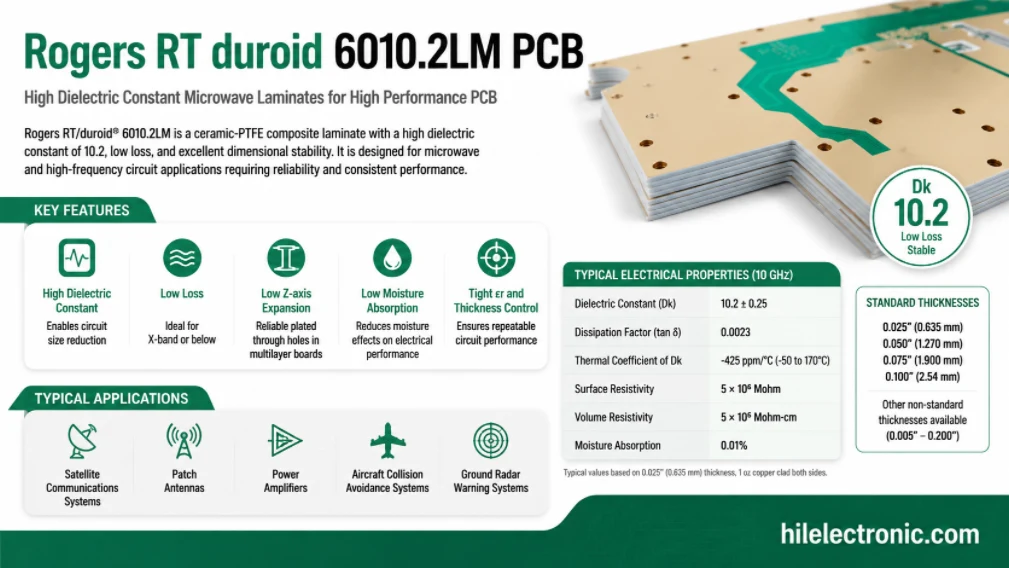
Rogers RT/duroid 6010.2LM PCB Manufacturer and Fabrication Service
Table of contentsIs RT/duroid 6010.2LM the Right Material...
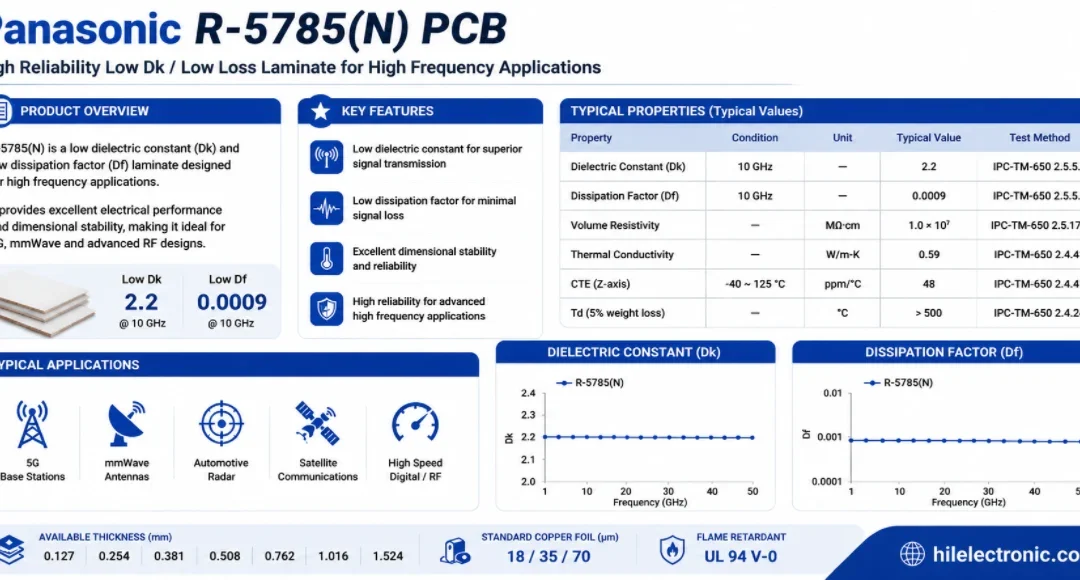
Panasonic R-5785(N) MEGTRON 7 PCB Manufacturer and Fabrication
Table of contentsWhen a Design Should Move to R-5785(N) /...
How to get a quote for PCBs
Let us run DFM/DFA analysis for you and get back to you with a report.
You can upload your files securely through our website.
We require the following information in order to give you a quote:
-
- Gerber, ODB++, or .pcb, spec.
- BOM list if you require assembly
- Quantity
- Turn time