
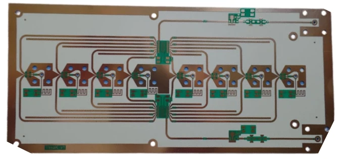
Rogers RO3010 PCB for RF Circuits and Antenna Boards

Rogers RO3010 is widely used in RF designs that need a high dielectric constant to reduce circuit size while keeping electrical behavior stable. It is especially relevant in compact antenna layouts, resonant microwave structures, and other high-frequency boards where the substrate directly affects how the circuit performs.
In these projects, the material itself is only part of the result. A custom Rogers RO3010 high dk PCB also depends on trace accuracy, stackup stability, plated transition quality, and controlled assembly. If those details are not managed carefully, the finished board may not match the intended RF response.
Highleap Electronics supports these builds through RF laminate selection, high-frequency PCB fabrication, and assembly for RF hardware, helping teams move from material choice to finished product with fewer surprises in production.
In This Article
Why RO3010 is chosen for compact RF boards
The biggest reason engineers choose RO3010 is simple: its high dielectric constant allows RF structures to be physically smaller. That matters when the layout has to fit into a tight enclosure, when antenna geometry must stay compact, or when resonant sections need to be reduced in size without losing their intended behavior.
This is why a RO3010 RF circuit board maker is often supporting products that need both space efficiency and controlled RF performance. The benefit is not only electrical. A smaller structure can also make system packaging easier, especially in dense wireless modules and antenna-related products.
Still, compactness only helps if the finished board remains electrically consistent. On RO3010 designs, the board is often part of the RF function itself, so fabrication quality becomes part of the design result rather than a separate manufacturing step.
Where RO3010 performs best in antenna design
A RO3010 patch antenna board is one of the clearest examples of where this material works well. Patch antennas and similar resonant structures are strongly influenced by substrate properties, thickness control, and conductor geometry. If those variables shift too much, the final antenna can move away from its intended operating point.
RO3010 is also useful in compact feed structures, microwave resonators, and RF layouts where physical length and electrical length need to be balanced carefully. In these designs, a standard material may be easier to source, but it may not allow the same degree of size reduction or electrical predictability.
That is why many engineers prefer working with suppliers experienced in RF and microwave PCB builds and in selecting the right substrate structure for high-frequency boards before the stackup is finalized.
What makes high-Dk fabrication more demanding
A high dielectric Rogers PCB fabrication project requires tighter control than a routine multilayer board. High-Dk materials can make compact designs possible, but they also make the finished circuit more sensitive to physical variation. Trace width, dielectric thickness, plated transitions, copper profile, and surface finish can all influence the final RF response.
Because of that, a China Rogers RO3010 PCB manufacturer should not treat the job as a standard high-frequency order. The useful manufacturer is the one that reviews stackup details, identifies geometry-sensitive regions, and understands how production tolerances affect actual circuit behavior.
This is also why many teams compare RO3010 against other high-frequency material options before release. Once the material is fixed, the board should follow a disciplined controlled PCB manufacturing flow rather than a simple price-driven build path.
Key manufacturing checkpoints for RO3010 projects
For a useful Rogers RO3010 PCB fabrication quote, these checkpoints should be clear before production starts:
Laminate thickness
The dielectric thickness has to match the RF design assumptions closely enough to keep geometry-sensitive areas stable.
Trace definition
Etching accuracy matters because small conductor changes can alter resonant and impedance-sensitive structures.
Via transitions
Clean plated holes and consistent via structure help reduce performance drift in RF paths and feed regions.
Panel stability
Panel strategy should reduce distortion and support good dimensional repeatability across builds.
On RO3010 boards, these checkpoints matter because the material is usually chosen for designs that are compact and electrically sensitive at the same time. A supplier that controls them well is far more valuable than one that only offers a low unit price.
Assembly details that affect final RF performance
A Rogers RO3010 PCB assembly factory should handle these boards as RF hardware, not as generic SMT assemblies. Once connectors, shielding parts, active devices, and support circuitry are added, assembly quality becomes part of the electrical result. Placement accuracy, grounding continuity, stencil control, and thermal profile can all affect final consistency.
This is particularly important on boards that combine antenna sections with control or interface circuitry. Mechanical alignment near connector launches and tuned regions can influence real test results, not just visual assembly quality.
For that reason, many teams prefer one supplier to manage both bare board production and RF PCB assembly support. It reduces handoff risk and keeps fabrication notes, build priorities, and inspection expectations aligned from start to finish.
How to evaluate an RO3010 PCB supplier
A strong Rogers RO3010 antenna PCB supplier should be able to explain more than price and turnaround. The right supplier should understand stackup review, antenna-sensitive geometry, plated transition quality, and how prototype requirements connect to repeat production.
A quick turn Rogers RO3010 PCB prototype is valuable only when it is representative of the intended production build. Fast delivery helps during validation, but only if the board can be trusted. That is why a useful quote review often includes questions about tolerance control, material sourcing, and whether fabrication and assembly can be coordinated under one workflow.
For teams ready to move forward, Highleap’s online quote request page is the fastest way to begin that review and confirm whether the design is ready for prototype or production.

Recommended Posts

Rogers TMM6 PCB Manufacturing for Microwave Filters
Table of contentsWhy Microwave Filter Designers Use...

Taconic fastRise 27 Prepreg PCB Bonding and HDI Fabrication Service
Table of contentsWhat fastRise 27 Is—and What You Are...
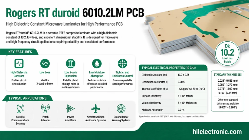
Rogers RT/duroid 6010.2LM PCB Manufacturer and Fabrication Service
Table of contentsIs RT/duroid 6010.2LM the Right Material...
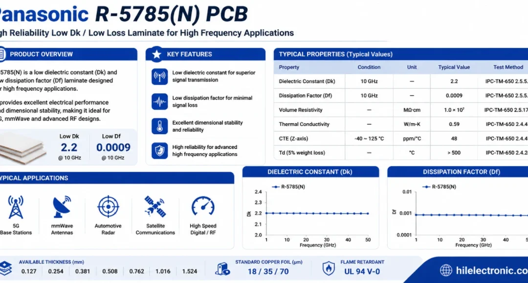
Panasonic R-5785(N) MEGTRON 7 PCB Manufacturer and Fabrication
Table of contentsWhen a Design Should Move to R-5785(N) /...
How to get a quote for PCBs
Let us run DFM/DFA analysis for you and get back to you with a report.
You can upload your files securely through our website.
We require the following information in order to give you a quote:
-
- Gerber, ODB++, or .pcb, spec.
- BOM list if you require assembly
- Quantity
- Turn time