
Humanoid Robotics PCB Design and Manufacturing

Humanoid robots push electronics harder than most automation systems. They combine high-DOF motion control, dense compute, high-speed vision, precision sensing, and high-current actuation in a compact body that constantly moves, vibrates, and experiences rapid load transients. That makes Humanoid Robotics PCB Design and Manufacturing fundamentally about one goal: keeping control, sensing, power, and communications stable and repeatable from prototype builds to mass production.
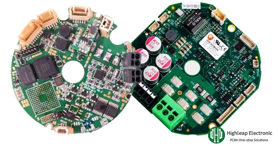
Highleap Electronics is a PCB manufacturing and PCB assembly factory supporting humanoid robot controller boards, joint drive PCBs, vision & sensor hubs, power distribution, battery management, and charging/docking electronics. We deliver integrated fabrication and PCBA with production-ready DFM, inspection, and functional validation to help robotics teams achieve consistent quality and stable supply.
Table of Contents
- Humanoid Robot Electronics Architecture
- Design Requirements: SI/PI, EMC, Thermal, Mechanical, Safety
- Key PCB Types in Humanoid Robots
- PCB Manufacturing for Humanoid Robotics
- PCB Assembly, Protection, and Integration
- Inspection, Testing, and RFQ Checklist
Humanoid Robot Electronics Architecture
A humanoid is a system-of-systems. High reliability is usually achieved by splitting electronics into purpose-built modules so that noisy power switching does not corrupt sensing, and high-speed interfaces do not suffer from unstable return paths or ground coupling. Most mature humanoid platforms converge on a “board set” that maps directly to functional subsystems:
- Main compute & AI: high-performance processing for perception, mapping, and planning; typically high-speed memory and multiple high-bandwidth links.
- Real-time controller: deterministic control loops, scheduling, synchronization, safety states, logging, and robust interfaces to drives and I/O.
- Distributed joint drives: compact servo/BLDC drive modules near joints, handling current sensing, switching stages, encoder feedback, and protection.
- Sensor hub: IMU, joint encoders, ToF/ultrasonic, tactile/pressure, temperature, and condition monitoring aggregation.
- Power & distribution: DC bus routing, fusing/protection, and conversion to stable rails for compute and sensors.
- Battery management & charging: pack monitoring, balancing, protection, and controlled charging/docking electronics.
- Comms & safety I/O: isolated I/O, emergency stop interfaces, interlocks, service/debug ports, and networking front-ends.
This architecture is not only about function—it is about stability. Joint drives create fast current transients and switching noise; vision and IMU need clean references; the controller needs deterministic timing and clean power integrity. The PCB strategy must support those realities from layout through production testing.
If you need integrated builds across this board set, Highleap supports complete delivery from PCB fabrication through PCB assembly, including consolidated scheduling and procurement via turnkey PCB assembly.

Design Requirements: SI/PI, EMC, Thermal, Mechanical, Safety
Humanoid robots compress high power, high speed, and precision sensing into a moving platform. The most common causes of field instability are not “component-level mistakes,” but system interactions: return-path issues, ground coupling, load-step droop, connector fatigue, thermal hotspots, and EMI injection into sensors or comms. The design priorities below address those failure modes directly.
Power Integrity (PI) and stable rails
- Load-step control: gait changes and joint acceleration create rapid transients; PDN design must keep rails stable without brownouts or sensor rail ripple.
- Decoupling strategy: combine bulk energy storage with high-frequency decoupling placed to match current loops and IC pin inductance.
- Power zoning: separate drive power from sensitive rails; isolate noisy domains and protect “quiet” analog/sensor supplies.
- Supervision & sequencing: predictable power-up/down avoids fault states and protects compute modules and storage.
Signal Integrity (SI) for high-speed links
- Impedance-controlled routing: stable stackups and controlled differential geometry for camera links, high-speed interconnects, and Ethernet.
- Return-path continuity: avoid reference plane breaks under critical links; ensure explicit return paths to reduce EMI and jitter.
- Connector transitions: preserve pair spacing and reference planes into connectors; avoid last-inch geometry surprises.
When multi-gigabit links or dense interfaces are involved, routing discipline and early stackup validation are essential. Many teams follow proven constraints from high-speed PCB design to protect margin before committing to volume.
EMI/EMC resilience in a switching, moving robot
- Switching loop minimization: reduce high di/dt loops in power stages to lower radiation and susceptibility.
- Filtering at cables and ports: add ESD/transient protection and common-mode filtering where external wiring exists.
- Partitioning and shielding provisions: plan shielding footprints, chassis bonds, and keep-outs alongside mechanical constraints.
- Sensor noise immunity: keep analog conditioning and IMU references away from switching nodes; use controlled grounding and routing.
Thermal robustness and derating
- Real heat flow design: copper spreading, thermal vias, and heatsink interfaces must match true dissipation, not nominal values.
- Hotspot management: place high-loss components with airflow and conduction paths in mind; avoid heat stacking near joints.
- Monitoring for protection: temperature sensors near high-stress areas support safe behavior and diagnostics.
Mechanical reliability under vibration and repeated motion
- Connector anchoring: reinforce high-mass connectors and provide strain relief planning for harness loads.
- Component reinforcement: inductors, tall capacitors, and heatsinked parts may need staking/adhesives and mechanical keep-outs.
- Board edge and mounting: hole tolerances, plating, and standoff strategy matter for long-term vibration exposure.
Safety and fault containment
- Predictable fault response: drives must fail safely, controllers must handle watchdog resets, and power must shut down cleanly.
- Isolation where required: use galvanic isolation and controlled ground strategy for safety I/O and noisy power boundaries.
- Traceability and test coverage: stable production requires repeatable inspection and documented process control.
Key PCB Types in Humanoid Robots
Humanoid robots rely on multiple PCB families, each with distinct constraints. Designing and manufacturing these boards as a coherent set improves stability and makes production scaling far smoother.
Main control / controller board PCBs
- Compute + real-time domains: high-level planning and perception alongside deterministic control, safety logic, and synchronization.
- Interface robustness: protection and filtering for external ports, long cable runs, and distributed modules.
- DFT readiness: programming headers, test points for key rails, and clear access zones for debug and production test.
Joint drive and motion control PCBs
- Switching stage stability: layout is part of the power stage; minimize inductance and manage ringing/EMI.
- Current sensing accuracy: Kelvin connections and noise-aware routing preserve control stability under transients.
- Protection behavior: overcurrent/overvoltage/thermal protection with predictable fault reporting to the controller.
Drive PCB best practices for layout and reliability are often guided by production-proven constraints from motor driver PCB and high-power handling recommendations in power electronics PCB.
Vision boards and sensor hub PCBs
- Vision links: high-speed routing discipline, robust connectors, and stable sensor rails to prevent intermittent perception faults.
- IMU and mixed-signal: clean references, controlled grounding, and separation from switching domains to protect accuracy.
- Feedback capture: encoder inputs and conditioning designed for noise, cable coupling, and dynamic motion.
Power distribution, battery management, charging and docking
- Power distribution boards: fusing, monitoring, connector strategy, and controlled returns for system stability.
- BMS electronics: monitoring, balancing, protection, and pack communications aligned to robotics duty cycles.
- Charging/docking: contact detection, protection, and controlled charge behavior; contactless power when applicable.
For mobile humanoids, battery and charging electronics are often major contributors to field reliability. Many teams reference battery management PCB design considerations and docking strategies such as wireless charging PCB solutions.
Interconnect and packaging: rigid-flex where it matters
Humanoids often require wiring through joints, torsion points, and compact volumes (neck, waist, shoulders, wrists, hands). Reducing connector count can improve long-term reliability, especially under repeated motion. Many programs adopt rigid-flex PCB designs for compact routing, fewer failure points, and cleaner assembly—when bend radius, reinforcement, and mechanical constraints are engineered in from the start.
PCB Manufacturing for Humanoid Robotics
In humanoid robots, fabrication quality directly impacts signal integrity margin, via reliability, and long-term stability. A manufacturing plan should be aligned to assembly, thermal constraints, and test strategy—especially for dense controllers and compact joint drives.
Stackups, impedance, and repeatability
- Defined stackups: lock stackup targets early to protect impedance control and SI/PI assumptions.
- Process repeatability: stable dielectric thickness and copper uniformity support consistent high-speed performance across lots.
- Controlled impedance builds: manufacturing validation should confirm impedance targets before scaling volume.
HDI and density management for compact modules
Dense compute boards and small form-factor sensor modules often require advanced via structures to escape fine-pitch packages and keep critical interconnects short. Many humanoid designs benefit from HDI PCB manufacturing to reduce via congestion, improve routing efficiency, and protect high-speed signal quality.
High-current copper strategy and via reliability
- Copper distribution: use multi-layer spreading and robust pours for current handling and thermal conduction.
- Via integrity: plating thickness, aspect ratio, and drill quality are critical for vibration and thermal cycling exposure.
- Selective heavy copper: when current density is the constraint, heavy copper PCB options can improve current carrying and thermal robustness when coordinated with assembly constraints.
Highleap supports fast-turn prototypes through stable volume production via integrated PCB fabrication planning with DFM feedback aligned to assembly and test requirements.
PCB Assembly, Protection, and Integration
Humanoid robot PCBA must survive vibration, shock, dust, humidity, and repeated motion—while keeping high-speed links and precision sensing stable. Assembly process control is often the difference between “works on the bench” and “stays stable in the field.”
PCBA controls that protect yield and reliability
- Fine-pitch SMT control: stable paste printing and reflow for BGAs/QFNs on controller and sensor boards.
- Mixed technology assembly: SMT + through-hole for high-current connectors, power parts, and mechanically stressed components.
- Thermal interface readiness: heatsinks/pads and keep-outs aligned with mechanical constraints and assembly sequence.
- Reinforcement strategy: staking/adhesives for inductors, tall caps, and connectors where vibration and harness loads exist.
Environmental protection for real-world deployment
Depending on deployment conditions, coatings help protect PCBA from moisture, dust, and contamination. Selection should balance protection, reworkability, and thermal behavior. Manufacturing teams often align coating choices with proven conformal coating practices and well-defined masking/coverage rules.
From PCBA to turnkey delivery
Many humanoid programs require integrated procurement, controlled substitutions, and consistent builds across multiple boards. Highleap supports consolidated delivery through turnkey PCB assembly to reduce vendor handoffs and stabilize schedule control from prototype to production ramp.
Inspection, Testing, and RFQ Checklist
Humanoid robots are sensitive to intermittent faults—marginal solder joints, connector issues, hidden voiding on thermal pads, and subtle power integrity problems can become “random” behaviors in the field. A layered inspection and test strategy catches these issues early and protects long-term reliability.
Inspection and test coverage that matters
- X-ray inspection: essential for BGAs/QFNs and hidden joints on controller and sensor boards; see X-ray inspection.
- ICT: verifies components and nets quickly to prevent escapes; see in-circuit testing (ICT).
- Functional testing (FCT): validates power sequencing, comms, sensor readouts, and drive interfaces under realistic conditions; see PCB functional testing.
- Testability in design: test points for rails and key signals, programming headers, access clearances, and consistent labeling across revisions.
Reliability validation (recommended for humanoid duty cycles)
- Thermal cycling: stresses solder joints and vias across repeated temperature swings.
- Vibration/shock screening: validates reinforcement strategy for connectors and power components, especially in joint-mounted drives.
- Burn-in where appropriate: helps catch early-life failures in power and compute assemblies.
- ESD/transient robustness: validates external ports and cable-connected modules for service and field wiring exposure.
RFQ checklist for fast, accurate quoting
- PCB data: Gerber/ODB++, drill files, board thickness, copper weight, impedance targets, and stackup requirements.
- BOM: manufacturer part numbers, approved alternates, and any controlled/traceable components.
- Assembly package: pick-and-place file, assembly drawings, polarity notes, and special process requirements (reinforcement, coating, thermal pads).
- Programming and test: firmware loading needs, ICT/FCT requirements, fixtures, and acceptance criteria.
- Environment targets: vibration level, temperature range, duty cycle, contamination exposure, expected service life.
- Quantity plan: prototype quantity, pilot run, and forecast for stable sourcing and scheduling.

Recommended Posts

Hall Effect Keyboard PCB Manufacturing & PCBA
Table of contentsHall Effect Keyboard PCB Buying...

ZMK Keyboard PCB Manufacturing & Assembly
Table of contentsZMK Wireless Keyboard PCBA Procurement...

Wireless Mechanical Keyboard PCB Manufacturing
Table of contentsWireless Keyboard PCB Procurement...

Split Keyboard PCB Manufacturing & Assembly
Table of contentsSplit Keyboard PCBA Procurement...
How to get a quote for PCBs
Let us run DFM/DFA analysis for you and get back to you with a report.
You can upload your files securely through our website.
We require the following information in order to give you a quote:
-
- Gerber, ODB++, or .pcb, spec.
- BOM list if you require assembly
- Quantity
- Turn time
In addition to PCB manufacturing, we offer a comprehensive range of electronic services, including PCB design, PCBA (Printed Circuit Board Assembly), and turnkey solutions. Whether you need help with prototyping, design verification, component sourcing, or mass production, we provide end-to-end support to ensure your project’s success. For PCBA services, please provide your BOM (Bill of Materials) and any specific assembly instructions. We also offer DFM/DFA analysis to optimize your designs for manufacturability and assembly, ensuring a smooth production process.