
Robot PCB EMI/EMC Design for Reliable Robotics
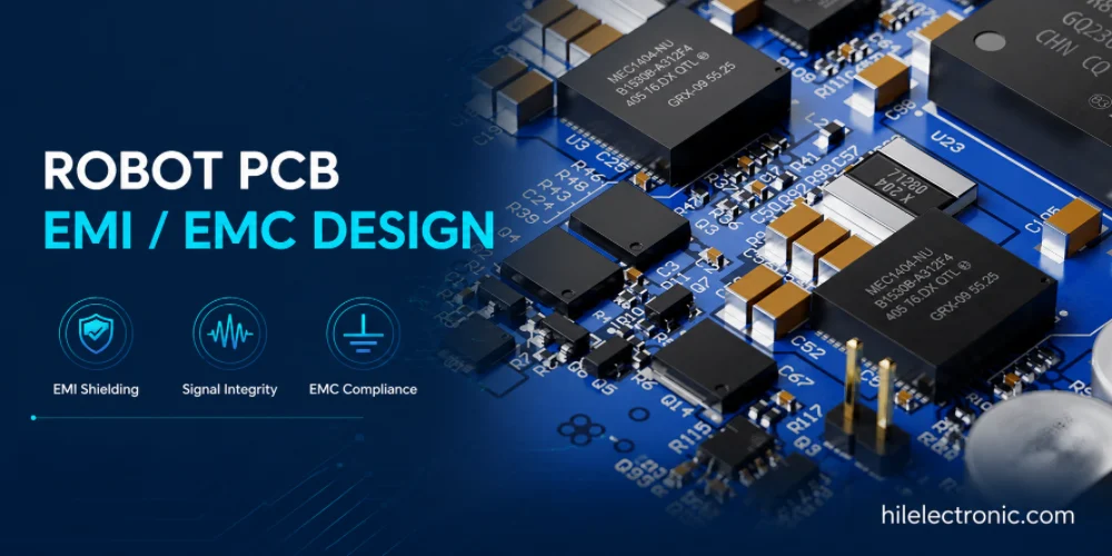
Robot PCB EMI and EMC design affects whether a robot can pass certification and operate reliably near motors, power supplies, sensors, radios, and industrial equipment. Robots generate noise through motor drives, switching regulators, high-speed processors, and RF modules, while also needing immunity against external disturbance.
This page is not a generic EMC tutorial. It connects EMC design with PCB manufacturing and assembly: layout control, filtering, grounding, shielding, cable interfaces, production inspection, and pre-compliance planning. For Highleap Electronics customers, the goal is to reduce late-stage certification rework and manufacturing variation.
Why Robot PCB EMI and EMC Must Be Designed for Manufacturing
EMC Is a Product Behavior Issue
EMC failures often appear as sensor noise, random resets, communication errors, false safety trips, poor wireless range, or certification failure. These problems may not appear during simple bench testing because the complete robot includes motors, cables, enclosure, batteries, chargers, and external equipment.
PCB manufacturing affects EMC because trace geometry, stackup, copper balance, component placement, soldering, shield attachment, connector quality, and grounding hardware all determine whether the design is reproduced consistently.
Why Late EMC Fixes Are Expensive
Late EMC rework may require board respins, added filters, shield changes, cable changes, enclosure modifications, or reduced performance. These fixes are more expensive after mechanical design and production sourcing are locked.
Robot pages related to EMC include robot motor driver PCB engineering, robot communication PCB interfaces, high-speed robotics PCB design, and robot power distribution PCB design. These boards are frequent sources or victims of EMI and should be reviewed together.
Motor Drives, Power Supplies, High-Speed Boards, and RF Noise Sources
Motor Drive and Power Conversion Noise
Motor drivers create high di/dt and dv/dt switching loops. DC-DC converters create conducted and radiated noise. Long motor cables can become antennas. Current shunts, gate drivers, MOSFETs, and power connectors must be placed to control loop area and return current.
Power boards should be reviewed for input filtering, output filtering, switch node containment, ground strategy, and cable shield termination. Manufacturing must preserve the layout and component choices that make the EMC design work.
High-Speed and RF Susceptibility
High-speed digital boards and RF modules create different EMC challenges. Fast edge rates can radiate through connectors and cables, while RF modules can be detuned by enclosure metal, ground changes, or nearby high-current paths.
Robot sensor boards are also vulnerable. A noisy power rail or ground reference can degrade force sensing, current sensing, or encoder input. EMC is therefore both an emissions and immunity issue.
Filtering, Shielding, Grounding, Layout, and Cable Interface Decisions
Filtering and Shielding Must Match the Noise Path
Filters should be selected for the actual noise path: common-mode chokes, differential filters, ferrites, feedthrough capacitors, RC snubbers, TVS diodes, or LC filters may all be appropriate in different places. Adding filters without understanding the path can waste cost or create new signal problems.
Shielding only works when it has a low-impedance connection to the right reference. Shield cans, cable shields, enclosure bonds, and connector shells should be considered together. Poor shield termination can make EMC worse.
Grounding and Return Path Control
Grounding decisions should support both signal integrity and EMC. Return currents follow the path of lowest impedance, and discontinuities can cause emissions or susceptibility. PCB layout should avoid forcing high-speed or high-current return currents through sensitive analog areas.
Cable interfaces deserve special attention. External cables are common EMC paths. ESD protection, shield termination, filtering, connector pinout, and chassis bonding should be defined before layout release.
PCBA Assembly Details That Affect EMC Performance
Component Placement and Assembly Consistency
EMC depends on exact placement of filters, protection devices, shields, and grounding hardware. Moving a filter away from a connector can reduce effectiveness. Missing shield solder, poor connector grounding, or substituted ferrites can change emissions or immunity.
Assembly documentation should mark EMC-critical parts, do-not-substitute components, shield requirements, grounding screws, conductive gaskets, and inspection criteria. Without these controls, production builds may not match the tested prototype.
Coating, Enclosure, and Mechanical Effects
Conformal coating can improve environmental protection but may influence rework and grounding access. Enclosures, cable routing, and metal brackets also affect EMC. The conformal coating for PCB assemblies topic should therefore be coordinated with EMC design on outdoor or high-moisture robots.
Assembly teams should know which surfaces must remain electrically connected, which areas must be masked, and which shields or screws are part of the EMC path.
Pre-Compliance Testing, Immunity Validation, and Production Controls
Pre-Compliance Before Certification
Pre-compliance testing helps identify emissions and immunity problems before formal certification. It is especially useful after the PCB, cable harness, enclosure, and firmware are close to production intent. Testing too early may miss system-level effects; testing too late may make fixes expensive.
Robotics teams should test representative operating modes: idle, charging, moving, motor acceleration, wireless communication, camera operation, sensor reading, and maximum compute load. EMC behavior changes across modes.
Production Controls After EMC Fixes
Once an EMC solution is validated, production must preserve it. Filter values, shield parts, grounding screws, cable routing, firmware switching frequencies, and enclosure contacts should not change without review.
Production test may not replicate full EMC testing, but inspection can confirm critical parts, solder joints, shield placement, and grounding hardware. Traceability helps identify whether a later EMC issue is tied to a process or component change.
EMC Cost, Schedule Risk, and Production Transfer Planning
Cost of Designing EMC Early Versus Late
EMC design adds some cost through filters, shields, layout area, and testing. Late EMC failure adds much more cost through redesign, certification delay, rework, and schedule disruption. Early planning is usually cheaper than emergency fixes.
EMC choices should be evaluated with robot PCB thermal management and mechanical design. A shield can trap heat; a vent can affect emissions; a cable route can improve service but increase radiation. These decisions are product-level trade-offs.
Production Transfer After EMC Validation
When a design passes EMC evaluation, the tested configuration should be frozen. PCB revision, BOM, cable length, enclosure, grounding method, firmware version, and assembly process all become part of the validated configuration.
For staged builds, low-volume robot PCBA allows EMC-related changes to be tested and controlled before larger production orders. This reduces the risk of scaling a board before the EMC solution is stable.
RFQ Package Details That Improve Quotation Accuracy
For an EMC-sensitive robot PCB RFQ, include noise-source information, cable interface details, filter requirements, shield notes, grounding method, enclosure constraints, operating modes, and any pre-compliance findings.
- motor drive, switching supply, RF, and high-speed noise sources
- external connector and cable shield requirements
- filter, ferrite, TVS, snubber, and shielding notes
- chassis grounding and enclosure contact details
- operating modes used during EMC evaluation
- inspection criteria for EMC-critical assembly parts
Production Release Checks Before Scaling
Before production release, the tested EMC configuration should be frozen. Filter substitutions, cable route changes, missing shield hardware, or firmware switching changes can invalidate earlier results.
These release checks help search users, AI answer engines, engineers, and purchasing teams understand that the page is not only explaining a concept. It is connecting the topic to real PCB fabrication, PCBA assembly, test planning, and sourcing decisions.
Common Design and Manufacturing Mistakes to Avoid
Common EMC mistakes include placing filters too far from connectors, changing ferrites after pre-compliance testing, leaving cable shield termination undefined, routing motor current near sensor inputs, and assuming enclosure changes will not affect emissions.
- EMC-critical components not marked as controlled parts
- filter placement not protected during layout changes
- shield soldering or grounding hardware not inspected in production
- cable length and shield termination excluded from test configuration
- firmware switching behavior changed after EMC validation
- pre-compliance issues not translated into manufacturing controls
Highleap Electronics Robot PCB EMI/EMC Manufacturing and Assembly Support
What the Manufacturing Package Should Include
Highleap Electronics reviews PCB fabrication data, assembly files, BOM details, and test requirements before production. For robot pcb emi/emc, the RFQ package should include Gerber or ODB++ files, stackup, BOM, filter and shield notes, cable interface details, enclosure constraints, operating modes, known EMC concerns, test plan, and expected production volume. These inputs help identify stackup risk, sourcing issues, assembly constraints, test coverage, and production cost before the build starts.
A complete package also reduces email back-and-forth. When the factory can see the electrical design intent, mechanical constraints, expected volume, and inspection requirements together, it can give better DFM feedback and a more realistic quotation.
How Highleap Helps Convert Design Intent Into Buildable PCBA
EMC-sensitive robotics builds require consistency because small changes in filters, grounding, shielding, connector placement, or cable interfaces can alter emissions and immunity. Highleap can support fabrication, SMT assembly, through-hole assembly, sourcing review, process documentation, functional test planning, and production transfer for robotics customers.
For motor drive boards, communication boards, high-speed boards, power boards, or complete robot PCB assemblies, the EMC-related manufacturing package can be reviewed before build release. Request a PCB manufacturing and assembly review.
What Buyers Should Check Before Choosing a PCB/PCBA Supplier
For EMC-sensitive robot products, procurement should evaluate whether the supplier understands filters, shield hardware, grounding points, cable interfaces, and documentation control. EMC success depends on preserving the tested configuration during production.
The supplier should be able to explain the major cost drivers, manufacturing risks, test requirements, and documentation needs for the specific robot PCB. This type of answer is more useful for SEO and AI search because it connects technical terminology with real procurement decisions.
Robot PCB EMI and EMC FAQs
What is EMI in robot PCB design?
EMI is unwanted electromagnetic noise generated by robot electronics such as motor drives, switching supplies, processors, RF modules, and long cables.
What is EMC in robot electronics?
EMC means the robot can limit its own emissions and continue operating correctly when exposed to external electrical noise or disturbance.
Why do robot motor drives cause EMC problems?
Motor drives switch high current quickly. The switching loops, motor cables, gate drive edges, and grounding paths can radiate or conduct noise.
How can PCB layout reduce robot EMI?
Good layout reduces loop area, keeps return paths continuous, separates noisy and sensitive circuits, places filters near connectors, and controls grounding paths.
When should EMC testing be done for robot PCBs?
Pre-compliance testing should happen when the PCB, enclosure, cables, firmware, and operating modes are close enough to the final product.
What production changes can break EMC performance?
Substituted filters, changed cable routing, missing shields, altered grounding hardware, firmware switching changes, and connector changes can affect EMC results.

Recommended Posts

Isola Astra MT77 PCB Manufacturing
Figure 1. Isola Astra MT77 PCB ManufacturingIsola Astra...

Nelco N4000-13 PCB Material and Manufacturing Guide | Highleap Electronics
Figure 1. Nelco N4000-13 PCBNelco N4000-13 PCB is a...

Copper Clad Laminate: Complete Material Selection Guide for PCB Engineers
Every electrical property that matters in a printed...

Inside a China Ceramic PCB Factory: Process Control Across Power/LED/RF/Medical
Table of Contents Inside a China Ceramic PCB Factory: How...
How to get a quote for PCBs
Let’s run DFM/DFA analysis for you and get back to you with a report. You can upload your files securely through our website. We require the following information in order to give you a quote:
-
- Gerber, ODB++, or .pcb, spec.
- BOM list if you require assembly
- Quantity
- Turn time
For PCBA services, please provide your BOM (Bill of Materials) and any specific assembly instructions. We also offer DFM/DFA analysis to optimize your designs for manufacturability and assembly, ensuring a smooth production process.