
ITEQ IT-968G PCB for Switch, Telecom and Hybrid Radar Boards
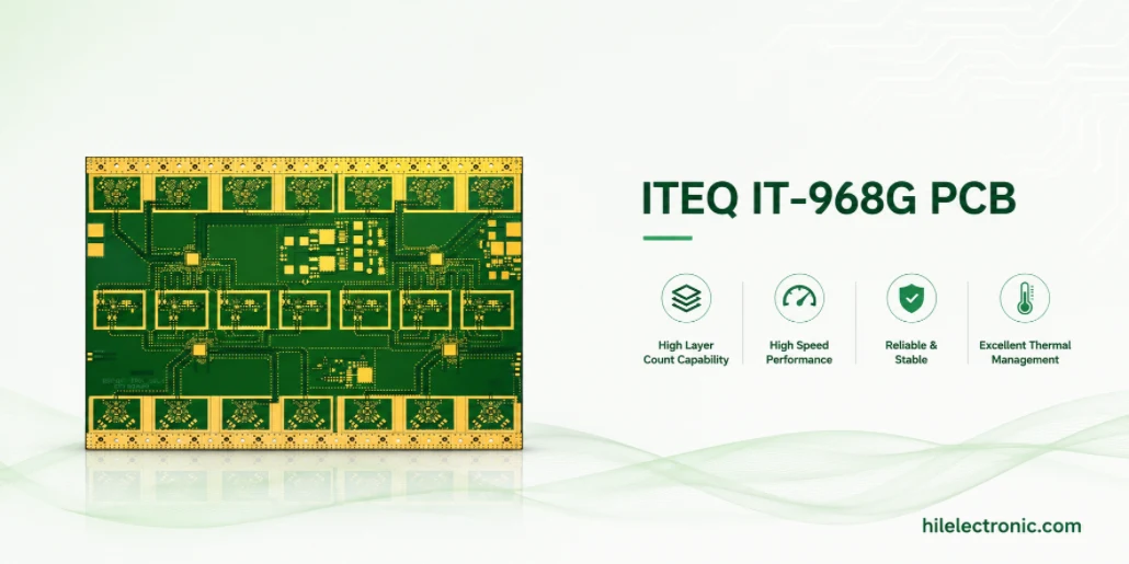
ITEQ IT-968G is most useful when the engineering team needs more channel margin than mainstream high-speed FR-4 can provide but does not automatically need the cost, supply-chain commitment, or processing discipline of the lowest-loss tier. Its value is not that it is “almost IT-988GSE.” Its value is that it can be the lowest material tier that still closes the complete channel with production guard band.
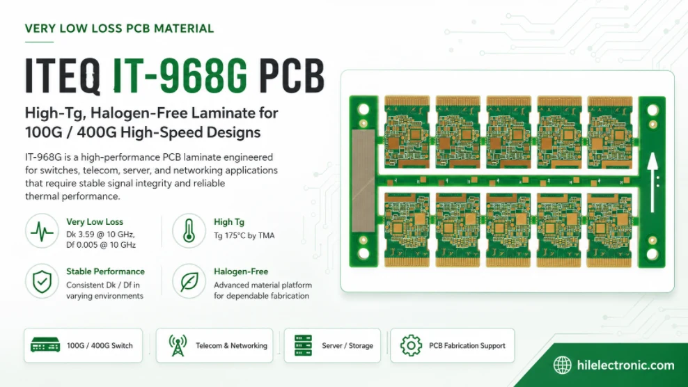
The current ITEQ datasheet identifies IT-968G as a high-Tg, halogen-free, ultra-low-loss laminate and prepreg system for 100G/400G switch solutions. It publishes construction-dependent values: at 10 GHz, typical Dk is 3.59 at 55% resin content and 3.26 at 70% resin content, while typical Df is 0.0050 and 0.0039, respectively. The same datasheet lists Tg 175°C by TMA, Td 400°C, T260 and T288 greater than 60 minutes, and 2.3% total z-axis expansion from 50–260°C. These values demonstrate why the exact construction—not the family name alone—must enter the stackup model.
IT-968G as the Performance-Sufficient Middle Tier
A material hierarchy is useful only if it is tied to route reach and discontinuity count. IT-968G can fit switch cards, line cards, storage controllers, base-station digital sections, automotive processing boards, control planes, and moderate-reach backplanes where the board contributes meaningful loss but the channel is not at the extreme end of length or connector density.
The phrase “performance sufficient” is not a downgrade. It is a disciplined design result. A lower-cost material that meets the worst-case channel with margin is the correct engineering choice. A more expensive material is justified only when it recovers required margin, enables a longer route, supports a roadmap, reduces system complexity, or improves yield enough to offset its cost.
| Decision dimension | Why IT-968G can be the right level | Warning sign that another tier is needed |
|---|---|---|
| Route length | Moderate on-board and card-to-card routes can benefit from very-low-loss behavior without the longest-backplane premium. | The longest path remains attenuation-limited after VLP copper, topology optimization, and backdrill. |
| Connector count | One well-designed connector and limited transitions may leave adequate margin. | Multiple large connectors and launches consume much of the return-loss and insertion-loss budget. |
| Lane rate/modulation | Many 25G, 56G, and selected 112G-class routes can be viable depending on reach and topology. | PAM4 margin is narrow, the route is long, or a 224G-class roadmap must use the same platform. |
| Layer count | High layer count can be supported with strong thermal and CAF properties. | Very large format, deep backdrill, HDI, or unusual construction needs a platform with broader construction data or lower loss. |
| Cost and availability | A widely processable ITEQ material may reduce qualification and sourcing burden. | Regional supply, glass style, copper, or prepreg availability cannot support the released build. |
The lowest passing tier is usually the most robust commercial choice
Over-specification can create its own risks: limited sources, longer material lead time, lower panel utilization, unfamiliar lamination behavior, more expensive scrap, or dependence on a foil that is not normally stocked. Those risks should be counted alongside electrical margin. The team should document why IT-968G is sufficient, not merely why a more expensive alternative exists.
Classify the Route Before Choosing the Laminate
The material decision should be made by route class. A design may contain short memory interfaces, medium SerDes links, long connectorized channels, clock lines, control buses, power planes, and lower-frequency RF on the same board. Applying one laminate assumption to every path hides the real cost driver.
| Route class | Typical characteristics | Material question |
|---|---|---|
| Short local digital | One package-to-package connection, few vias, no connector, short electrical length. | Can a reliable mid-loss or low-loss material pass with margin? IT-968G may be unnecessary. |
| Moderate high-speed card route | One or two package escapes, several vias, moderate length, controlled VLP copper. | Does IT-968G meet the channel mask across process corners? This is a common sweet spot. |
| Long line-card or chassis route | Long stripline, connector launch, backdrill, tighter PAM4 margin. | Compare IT-968G with IT-988GSE or equivalent using the same topology and copper. |
| Backplane-scale route | Multiple connectors, long board segments, many transitions, high layer count. | A lower-loss tier or platform material may be needed; model the complete package-to-package channel. |
| RF support/control | Lower-frequency RF, LO distribution, control, power, or digital processing around a radar/radio module. | IT-968G may be appropriate if frequency-specific performance and layout support it. |
| Radiating 76–81 GHz antenna/feed | Patch array, coupler, feed network, phase-critical mmWave routing. | Use a dedicated radar/mmWave material such as IT-88GMW or another validated construction unless data prove otherwise. |
Each route class should have a maximum length, permitted via count, connector assumptions, target layer, copper profile, and electrical mask. That table becomes the bridge between architecture and high-speed stackup. It also prevents late routing changes from silently pushing a previously safe IT-968G channel into a class that requires a lower-loss material.
When IT-968G Is Enough—and When IT-988GSE Is Justified
IT-968G is enough when the complete channel remains inside all limits after tolerances, temperature, and manufacturing variation are included. Df is not the pass/fail criterion. The channel must satisfy insertion loss, return loss, crosstalk, mode conversion, skew, jitter, and any protocol-specific compliance requirement.
| Observation | Interpretation | Action |
|---|---|---|
| Straight-line loss is comfortably below the mask; failures are at launches | The material is not the primary problem. | Tune BGA, connector, antipad, return-via, and reference-plane transitions before upgrading. |
| IT-968G passes nominally but fails at worst-case etch/thickness/roughness | The stackup lacks production guard band. | Improve geometry and process control, or compare the margin recovered by IT-988GSE. |
| IT-968G with VLP copper and optimized vias passes all routes | The middle tier is sufficient. | Freeze construction, validate coupons, and avoid an unnecessary material escalation. |
| Only the longest route fails because of distributed attenuation | A lower Df may directly address the residual problem. | Model IT-988GSE, MEGTRON 7N, or another candidate on the identical construction. |
| The roadmap adds 224G PAM4 without changing board geometry | Current margin may not support the next generation. | Run a roadmap study using higher-frequency material data and connector/package models. |
| The substitute has a lower datasheet Df but rougher copper or different glass | Datasheet comparison is not construction comparison. | Use measured coupon loss and process data before approving equivalence. |
Use lane length, connector count, roughness, and equalization together
A route-length limit stated without connector count is incomplete. A connector-count limit stated without via topology is also incomplete. Equalization can extend reach, but it cannot erase deep reflections or crosstalk. A practical selection worksheet includes lane rate, modulation, baud rate, route length per layer, package and connector models, via count, residual stubs, copper profile, field-solver geometry, transmitter FIR range, receiver equalization, and required system margin.
The result can be a simple color-coded matrix: green routes pass on IT-968G with margin; yellow routes require topology or process improvement; red routes require a lower-loss material or architecture change. This makes the material decision transparent to layout, SI, procurement, and manufacturing teams.
Define the Boundary Between Digital/RF Support and a 77 GHz Antenna Layer
IT-968G should not be described as ITEQ’s primary 76–81 GHz radar antenna material. ITEQ separately positions IT-88GMW for long-, medium-, and short-range automotive radar. That distinction matters because an antenna layer needs frequency-specific dielectric stability, tight dielectric-thickness control, copper-profile control, mask keep-outs, phase repeatability, and measured antenna correlation.
| Board function | IT-968G suitability | Required evidence |
|---|---|---|
| Radar processor and digital interface board | Potentially suitable for high-speed digital, memory, Ethernet, control, and power-support routing. | Normal high-speed channel, thermal, CAF, and assembly qualification. |
| Base-station digital/control section | Potentially suitable for moderate-reach SerDes and mixed control functions. | Construction-specific Dk/Df, loss budget, copper and via plan. |
| Lower-frequency RF support layer | Possible where frequency, loss, and stability requirements are demonstrated. | Frequency-relevant EM model and measured coupon; do not infer from the 10 GHz label alone. |
| 77 GHz patch array or feed network | Not the default choice; compare with IT-88GMW or another dedicated mmWave material. | 76–81 GHz design data, thickness tolerance, copper roughness, mask rule, antenna efficiency, phase and temperature correlation. |
| Hybrid radar/digital assembly | IT-968G can serve the digital section while a dedicated RF material serves the antenna section. | Hybrid cure, flow, CTE, registration, warpage, adhesion, and module-level RF qualification. |
Use IT-968G Intentionally in a Hybrid Stackup
A hybrid stack can use IT-968G for digital and control layers while reserving a radar or RF laminate for the radiating section. This can reduce cost and layer complexity, but it replaces a simple material decision with a lamination-system decision. Resin cure, flow, CTE, dimensional movement, copper balance, bond strength, and warpage must be qualified together.
- Define the bond interface. Identify which prepreg bonds IT-968G to the RF core, what resin volume fills copper topography, and whether the interface is compatible with both surfaces.
- Align cure windows. Confirm temperature, time, pressure, and vacuum conditions that fully cure the bonding system without damaging or over-stressing either material.
- Model dimensional movement. Different x-y CTE, glass systems, and resin shrinkage can shift RF-to-digital registration or create panel distortion.
- Balance copper and resin. Asymmetric copper or local cavity structures can increase bow, twist, and antenna-to-housing variation.
- Control drilling and desmear. The via wall may pass through multiple resin systems, so the desmear and plating process must create a reliable interface in all layers.
- Test the hybrid, not the ingredients. Thermal stress, IST or other interconnect tests, cross-sections, adhesion, warpage, and RF correlation should use the full stack.
A hybrid is most attractive when the RF area is localized and the digital section has many layers. It is less attractive when the panel contains a large, phase-sensitive antenna aperture and the material boundaries create complex registration or warpage. The cost model should include extra engineering, coupons, lamination trials, and lower initial yield.
Release Construction-Specific Dk, Df, Copper, and Thickness
The IT-968G datasheet illustrates the construction effect clearly: at 10 GHz, the 55% and 70% resin-content references have different Dk and Df. A solver input labeled only “IT-968G” is therefore incomplete. The stackup release must state the exact core/prepreg build and the source of the design values.
| Release item | Minimum definition | Why it matters |
|---|---|---|
| Core and prepreg | Exact IT-968G laminate and matching IT-968GB prepreg construction, glass style, resin content, cured thickness. | Determines effective dielectric behavior, resin fill, impedance, and lamination. |
| Dk/Df | Frequency, test method, resin content/construction, and whether the value is a datasheet reference or design correlation. | Prevents mixing RC55% and RC70% values or using one number across all layers. |
| Copper | Foil supplier/type, profile, base weight, treatment side, finished thickness, plating contribution. | Controls conductor loss, impedance, etch compensation, and peel/reliability behavior. |
| Impedance geometry | Finished top and bottom width, spacing, dielectric thickness, copper thickness, reference planes, tolerance. | Allows the field solver and factory to use the same geometry. |
| Glass and orientation | Glass style, spread-weave status, warp/fill or panel direction if relevant. | Supports skew analysis, registration, and repeatability. |
| Thermal/reliability | Tg/Td/CTE references, IPC slash sheet, assembly cycles, hole geometry, test plan. | Connects material capability to actual board and assembly stress. |
Do not create a single universal design Dk
A fitted Dk from one coupon is an effective model for that coupon’s geometry, copper, glass, and frequency range. It should not be copied to a different resin content or layer construction. Maintain a controlled material library indexed by construction and test method, and record any empirical tuning used to match measured S-parameters.
Factory Controls for Cost-Effective High-Speed Production
The commercial advantage of IT-968G depends on predictable production. A stackup that passes only with rare glass styles, special copper, or extremely tight etch can erase the cost benefit. The fabricator should propose a construction that is routinely stocked and demonstrate capability on the critical dimensions.
| Factory topic | Control focus | Cost/yield implication |
|---|---|---|
| Material availability | Approved core/prepreg combinations, standard panel sizes, copper options, regional source and lead time. | Avoids redesign or emergency substitution after layout release. |
| Lamination | Cured dielectric thickness, resin fill, registration, copper balance, press loading. | Thickness spread changes impedance; excessive trial cycles increase scrap. |
| Etch | Finished width and spacing capability on selected copper thickness/profile. | Overly tight geometry may require a more expensive process than a lower-loss material would. |
| Backdrill | Depth tolerance, drill wander, residual stub, keep-out to inner pads. | Deep or dense backdrill can dominate yield and channel variation. |
| Inner-layer treatment | Adhesion versus roughness trade-off. | A high-roughness treatment can consume loss margin intended to justify IT-968G. |
| Inspection/test | Cross-sections, TDR, S-parameter coupons, panel sampling. | Targeted evidence is cheaper than broad requalification after a field issue. |
A factory review should also identify which dimensions will be measured as process-control data rather than only on a final first article. For example, finished dielectric thickness, critical line width, backdrill residual stub, and coupon loss can be trended by lot. This is the evidence that supports stable performance at a middle material tier.
Verification Plan for a Performance-Sufficient Design
Verification should be proportional to the decision claim. If the claim is that IT-968G is “good enough,” the test must show adequate margin under representative manufacturing variation—not only that one nominal coupon passed.
- Build a correlated SI coupon. Use the released glass, copper, thickness, line geometry, and treatment. Include at least two lengths when launch de-embedding is important.
- Measure TDR and differential S-parameters. Confirm impedance, insertion loss, return loss, phase, and mode conversion over the required bandwidth.
- Cross-section the same panel. Record as-built dielectric thickness, copper, sidewall, via and backdrill geometry.
- Compare multiple panel locations. Include center/edge positions or other known process extremes.
- Run the worst route in the system model. Replace nominal line models with measured or correlated data and verify system margin.
- Test assembly exposure. Where reliability is important, include the planned reflow/rework history and inspect plated holes and delamination risk.
- Create a release baseline. Archive raw S-parameters, stackup, material lot, coupon artwork, process record, and acceptance limits.
A pass/fail decision should state the remaining margin and its uncertainty. If measured loss is close to the limit, the project should not declare success without understanding lot variation, fixture uncertainty, and temperature. A material upgrade may be cheaper than operating with no manufacturing guard band.
RFQ Checklist and Substitution Rules
The RFQ should preserve the middle-tier logic. It must prevent a supplier from replacing IT-968G with a generic high-Tg FR-4 based on Tg alone, while also allowing controlled equivalence when the same channel and reliability performance can be proven.
- Exact material: IT-968G laminate and matching IT-968GB prepreg, or an equivalent approved through the defined comparison route.
- Target application and route classes: lane rate/modulation, maximum lengths, connector/via assumptions, and sensitive layers.
- Stackup: exact glass styles, resin contents, core/prepreg thicknesses, copper profile and finished copper, total board thickness.
- Electrical acceptance: impedance, loss/return-loss coupon limits, test bandwidth, test fixture/de-embedding, crosstalk or skew where required.
- Mechanical/reliability: finished hole sizes, aspect ratios, minimum wall copper, backdrill, reflow count/profile, CAF or environmental needs.
- Process: inner-layer treatment, lamination, etch tolerance, registration, bow/twist, cleanliness, material storage and lot traceability.
- Substitution evidence: same-construction field-solver comparison, measured coupon data, thermal/reliability records, availability, and written approval.
Misuse Cases to Prevent
| Misuse | Why it is risky | Correction |
|---|---|---|
| Calling IT-968G a universal 100G/400G material | Aggregate throughput hides lane architecture and reach. | Define route classes and simulate the complete channel. |
| Using IT-968G on a 77 GHz radiator because the project is “radar” | The material is not the dedicated ITEQ radar product and the antenna requires band-specific validation. | Use IT-88GMW or another validated mmWave construction for the radiating layer unless evidence supports IT-968G. |
| Using the RC70% Dk for an RC55% layer | The datasheet shows materially different Dk/Df by resin content. | Release construction-specific values per layer. |
| Ignoring copper profile because the resin is low loss | Conductor roughness can consume significant margin. | Specify and model the production foil and treatment. |
| Upgrading to IT-988GSE before fixing stubs and launches | Localized discontinuities may dominate. | Correct topology, then recalculate residual distributed loss. |
| Allowing a generic “equivalent” in the PO | A supplier can match one property while changing the channel and reliability behavior. | Define measurable equivalence and an approval hold point. |
Used within these boundaries, IT-968G becomes a strong engineering and commercial choice: enough electrical performance for the routes that need it, enough thermal and CAF capability for high-layer production, and a clear escalation path when the longest or next-generation channels require IT-988GSE or another lower-loss platform.
Manufacturer references and release notes
The references below identify the current IT-968G construction-dependent comparison data, its switch-market positioning, and the separate IT-88GMW radar material. The production stackup should cite the exact controlled IT-968G datasheet revision, matching prepreg, foil, resin content, and approved fabricator construction.

Recommended Posts

Isola Astra MT77 PCB Manufacturing
Figure 1. Isola Astra MT77 PCB ManufacturingIsola Astra...

Nelco N4000-13 PCB Material and Manufacturing Guide | Highleap Electronics
Figure 1. Nelco N4000-13 PCBNelco N4000-13 PCB is a...

Copper Clad Laminate: Complete Material Selection Guide for PCB Engineers
Every electrical property that matters in a printed...

Inside a China Ceramic PCB Factory: Process Control Across Power/LED/RF/Medical
Table of Contents Inside a China Ceramic PCB Factory: How...
How to get a quote for PCBs
Let’s run DFM/DFA analysis for you and get back to you with a report. You can upload your files securely through our website. We require the following information in order to give you a quote:
-
- Gerber, ODB++, or .pcb, spec.
- BOM list if you require assembly
- Quantity
- Turn time
For PCBA services, please provide your BOM (Bill of Materials) and any specific assembly instructions. We also offer DFM/DFA analysis to optimize your designs for manufacturability and assembly, ensuring a smooth production process.