
Continuous Conduction Mode in SMPS

In the design and operation of Switched-Mode Power Supplies (SMPS), one critical concept that directly influences the performance, stability, and efficiency of the power supply is the conduction mode. Understanding continuous conduction mode (CCM) versus discontinuous conduction mode (DCM) is crucial, as these modes have significant impacts on the design and layout of electronic circuits, especially when integrated into PCBs. Here’s why CCM matters, how it affects your designs, and the steps involved in achieving it.
What is Continuous Conduction Mode?
Continuous conduction mode (CCM) is a condition in a switching power supply where the current in the inductor never drops to zero during the switching cycle. This is a preferred operating mode because it provides smoother energy transfer and reduces noise and ripple in the output. In contrast, in discontinuous conduction mode (DCM), the inductor current falls to zero between cycles, which can result in more complex behavior in terms of voltage regulation and noise.
In an SMPS, the mode of conduction affects both power delivery and the type of components you select, as well as the overall PCB layout. The current behavior during the switching cycles is crucial to how you manage signal integrity, minimize noise, and ensure efficient power conversion.
Why Does Continuous Conduction Mode Matter?
In addition to providing stable output voltage, CCM offers several significant advantages that improve the overall performance of power conversion systems. These benefits make it an attractive choice for a wide range of applications, especially those that demand precision, reliability, and efficiency. Understanding the importance of CCM helps engineers optimize designs for better control, lower noise, and increased efficiency, which are essential in modern electronic systems.
Stable Output Voltage:
In CCM, the output voltage is primarily controlled by the pulse-width modulation (PWM) duty cycle, providing greater control and stability. This makes it easier to manage output voltage even when the input voltage fluctuates or varies with load conditions. The consistent current flow helps maintain a predictable, reliable output, ensuring performance stability under diverse operational environments.
Reduced Noise and EMI:
Operating in CCM significantly reduces noise and electromagnetic interference (EMI) compared to Discontinuous Conduction Mode (DCM). Since the inductor current does not drop to zero in CCM, the current waveform remains smooth, eliminating the sharp transitions typical of DCM. This results in less EMI and makes the system more suitable for sensitive applications where noise reduction is critical.
Improved Efficiency:
CCM enhances energy efficiency by ensuring that the inductor continuously transfers energy between the input and output stages. Unlike DCM, where energy is stored and then discharged, CCM minimizes losses during this process, leading to a more efficient power conversion. This is particularly beneficial in applications requiring sustained high performance, reducing energy waste and thermal dissipation.
Simplified Control:
In CCM, the continuous current flow simplifies the control loop design. With no interruption in current, controlling the switching frequency and duty cycle becomes more straightforward. This simplicity translates into a more stable system, where regulation is easier to manage, and the power supply can adapt more quickly to varying conditions without complex adjustments.
Continuous Conduction Mode vs. Discontinuous Conduction Mode: The Impact on PCB Design
When designing a Switched-Mode Power Supply (SMPS), understanding whether the circuit will operate in Continuous Conduction Mode (CCM) or Discontinuous Conduction Mode (DCM) is crucial, as it influences not only the performance but also the PCB layout and component selection. Each mode brings its own set of challenges and requirements for efficient PCB design, especially regarding power handling, noise control, and ripple management.
Continuous Conduction Mode (CCM)
In CCM, the inductor current never drops to zero during the switching cycle. The current flows continuously, meaning the energy transfer between the input and output stages remains constant. This mode is preferred in designs where precise voltage regulation, low ripple, and lower electromagnetic interference (EMI) are critical.
Impact on PCB Design:
- Efficient Power Routing: As current remains continuous, PCB traces need to be designed to handle high current with minimal loss. Designers should use wider traces or thicker copper layers to reduce resistance and ensure efficient power delivery, preventing voltage drops that could affect performance.
- Reduced EMI: Since the inductor current stays smooth in CCM, the waveform avoids sharp transitions that typically cause EMI. For low EMI designs, PCB designers can focus on grounding techniques and shielding, using solid ground planes and proper component placement to ensure noise-free operation.
- Thermal Management: Continuous current flow leads to more consistent power dissipation. Effective thermal design becomes crucial, often requiring heat sinks, thermal vias, and higher-rated components to manage the heat generated by continuous operation.
Discontinuous Conduction Mode (DCM)
In DCM, the inductor current falls to zero during part of the switching cycle. This mode is common in low-power applications or when the load is light. While DCM can offer some advantages in terms of simpler operation for light loads, it introduces more ripple and EMI due to the sharp current transitions.
Impact on PCB Design:
- Complex Layout Design: The variable nature of the current in DCM requires a more flexible PCB layout. Inductor size, capacitor placement, and trace width must be carefully selected to handle the current peaks and valleys without causing instability or excessive losses.
- Increased Ripple and EMI: Since the current drops to zero, DCM circuits can experience greater ripple and EMI due to the abrupt changes in current. To manage this, high-quality decoupling capacitors and strong PCB grounding are essential. Additionally, shielding techniques and low-impedance ground planes should be optimized to minimize noise.
- Component Selection: In DCM, the component choice, especially inductors and capacitors, plays a critical role. Inductors should be chosen to handle the varying current demands, while capacitors must be sized large enough to suppress ripple effectively. Simulation tools like SPICE can help determine the ideal values for these components to avoid entering CCM when unintended.
The decision between CCM and DCM influences not just the efficiency and performance of your SMPS but also the PCB design strategy. CCM is generally preferred for applications requiring precise voltage regulation, low noise, and improved efficiency, whereas DCM is typically found in low-power, light-load designs that tolerate higher ripple and EMI. Understanding the mode your design will operate in allows you to optimize your PCB layout, select the right components, and implement the most effective noise and thermal management strategies to achieve the best possible performance.
If this requirement affects sourcing or production release, compare it with BGA PCB assembly and PCB prototype review before sending the final files for review.
Design Considerations for Achieving Continuous Conduction Mode
To design an SMPS that operates in continuous conduction mode, you must carefully choose the components and design the layout. Here are the key factors that influence CCM operation:
-
- Inductor Selection: The inductor plays a critical role in determining the mode of conduction. The inductance value needs to be high enough to prevent the current from dropping to zero. Typically, a larger inductor will dampen current ripples, which helps maintain continuous conduction.
- Capacitor Selection: Capacitors in the power supply circuit are used to smooth out voltage fluctuations and store energy. A sufficiently large output capacitor is necessary to prevent excessive ripple and ensure that the current does not drop to zero between cycles. The value of the output capacitance should be selected carefully to balance ripple suppression and ensure the design remains in CCM.
- Load Resistance: The load resistance directly affects the operating mode. When the load is too light, the system might enter DCM. By adjusting the load resistance, you can ensure that the inductor current remains above zero throughout the switching cycle.
- PWM Parameters: The switching frequency and duty cycle are also essential to CCM operation. Proper tuning of the PWM signal can help ensure that the inductor current stays continuous. Selecting the correct switching frequency and duty cycle is important for achieving both stable operation and energy efficiency.
- Simulation and Modeling: Using simulation tools like SPICE can help verify that your design will operate in CCM. These tools allow you to model the inductor current, voltage ripple, and other critical parameters to ensure the SMPS will meet your performance goals.
Conclusion
Achieving continuous conduction mode in SMPS designs is essential for improved efficiency, better voltage regulation, and reduced noise and EMI. The right choice of inductor, capacitor, and PWM parameters, combined with careful PCB design, will help ensure that your system operates in CCM, providing the best performance for high-tech applications.
At Highleap Electronic, we specialize in PCB manufacturing and assembly, offering expert solutions for power supply designs, including SMPS with continuous conduction mode. Our advanced manufacturing capabilities ensure that your high-performance power supplies are efficient, reliable, and ready for demanding electronic applications. Let us help you design and build the perfect power supply for your system, with the precision and quality your project demands.
Get a Free PCB & PCBA Quote

Recommended Posts

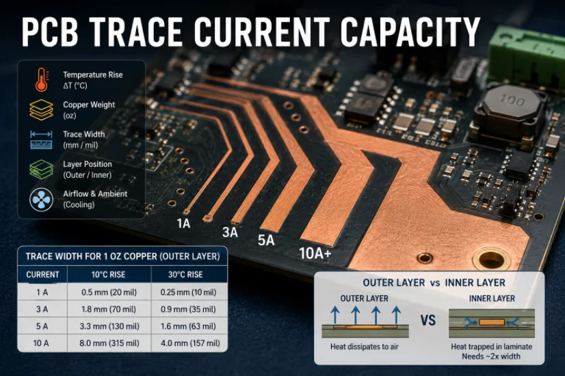
PCB Current Calculator: Sizing Trace Width and Vias with the IPC-2221 Formula
Figure 1. Pcb Current Calculator reference image for PCB...
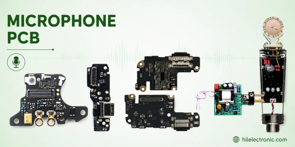
Microphone PCB Design: How the Board Itself Shapes Your Audio Quality
Figure 1. Microphone Pcb reference image for PCB...
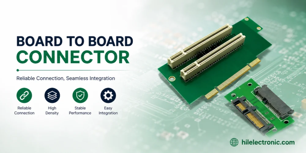
Board-to-Board Connector: Types, Specifications, and How to Select One
Figure 1. Board To Board Connector reference image for PCB...
PCB Trace Width Calculator: How to Size Traces for Current, Voltage Drop, and Impedance
Figure 1. A PCB trace width calculator is a starting point...
How to get a quote for PCBs
Let us run DFM/DFA analysis for you and get back to you with a report.
You can upload your files securely through our website.
We require the following information in order to give you a quote:
-
- Gerber, ODB++, or .pcb, spec.
- BOM list if you require assembly
- Quantity
- Turn time
In addition to PCB manufacturing, we offer a comprehensive range of electronic services, including PCB design, PCBA (Printed Circuit Board Assembly), and turnkey solutions. Whether you need help with prototyping, design verification, component sourcing, or mass production, we provide end-to-end support to ensure your project’s success. For PCBA services, please provide your BOM (Bill of Materials) and any specific assembly instructions. We also offer DFM/DFA analysis to optimize your designs for manufacturability and assembly, ensuring a smooth production process.