
PCB BOM Reconstruction Services | Extract BOM from Physical Board

Table of Contents
- What BOM Reconstruction Delivers and Why It Is Essential
- Component Identification: From Physical Marking to Verified Part Number
- The Complete BOM Reconstruction Methodology
- Handling Obsolete, Discontinued, and Unmarked Components
- BOM Verification and Cross-Referencing
- From BOM to Procurement: Sourcing Strategies
- Highleap’s BOM Reconstruction Services
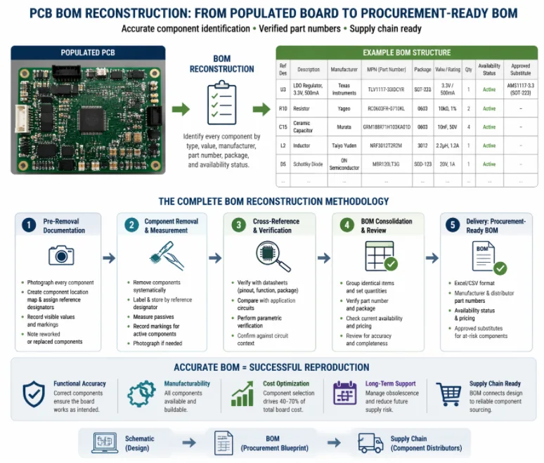
PCB BOM reconstruction is a highly specialized reverse-engineering process that transforms a populated circuit board into a complete, procurement-ready Bill of Materials (BOM). This exact procedure identifies every single component on the board by type, value, manufacturer, part number, package, and availability status.
The BOM is far more than a simple parts list: it is the procurement blueprint that connects the circuit design (schematic) to the physical supply chain (component distributors), and it is the single most important document that determines whether the reverse-engineered board can actually be built.
Accuracy is paramount. A BOM with even one incorrectly identified component can render the entire reverse engineering project useless. For example, an IC identified as a 3.3V regulator when it is actually a 5V regulator produces a board with incorrect voltage — potentially destroying downstream components at first power-on. A capacitor identified as 100 nF when it is actually 100 µF may cause a power supply to oscillate. Accuracy in BOM reconstruction is not a nice-to-have; it is the absolute foundation of a functional reproduction.
This guide provides a detailed, step-by-step methodology for professional BOM reconstruction from assembled PCBs, including advanced identification techniques for standard, obsolete, and completely unmarked components.
1) What BOM Reconstruction Delivers and Why It Is Essential
1.1 BOM Fields and Structure
A professional, manufacturing-ready BOM includes the following critical fields for each component:
| BOM Field | Example Data | Engineering Purpose |
|---|---|---|
| Reference Designator | U3 | Position on board — links the BOM directly to the schematic and layout |
| Description | LDO voltage regulator, 3.3V, 500mA | Functional identification for rapid engineering reference |
| Manufacturer | Texas Instruments | Original component manufacturer |
| Part Number (MPN) | TLV1117-33IDCYR | Exact procurement reference for the supply chain |
| Package / Footprint | SOT-223 | Physical footprint required for SMT assembly |
| Value / Rating | 3.3V / 500mA | Core electrical specifications |
| Quantity | 1 | Per-board quantity for accurate procurement scaling |
| Availability Status | Active / EOL / Obsolete | Assesses current supply chain viability |
| Approved Substitute | AMS1117-3.3 (SOT-223) | Reliable alternative for obsolete or out-of-stock components |
1.2 Why BOM Accuracy Matters
The integrity of the BOM directly determines four critical project outcomes:
- Functional Correctness: Whether the reproduced board functions correctly (a wrong component guarantees a wrong function).
- Manufacturability: Whether the board can be manufactured at all (unavailable components will block production).
- Cost Efficiency: Production cost (since component selection drives 40–70% of total board cost).
- Long-Term Supportability: Board lifespan (components nearing end-of-life create severe future supply risks).
2) Component Identification: From Physical Marking to Verified Part Number
2.1 Active Components (ICs, Transistors, Diodes)
The Standard Identification Flow:
- Visual Inspection: Read the package marking (including manufacturer logo, part number, date code, and lot code).
- Database Querying: Search the part number in authorized distributor databases (e.g., Digi-Key, Mouser, Octopart, LCSC).
- Datasheet Verification: Retrieve the datasheet and verify that the pinout, package, and function perfectly match the circuit context.
- Era Assessment: Cross-reference the date code to determine the manufacturing era (highly relevant for obsolescence assessment).
Handling Incomplete or Ambiguous Markings:
- SMD Code Cross-Referencing: Many IC manufacturers use internal marking codes that differ from the official part number. Cross-reference databases (such as the SMD Code Book, manufacturer marking guides, or online IC identification forums) map these top-codes back to full part numbers.
- Package and Pin Filtering: The package type and pin count narrow the candidate list. For instance, a 14-pin SOIC with a TI logo limits the search strictly to TI’s SOIC-14 product range.
- Circuit Context Analysis: Circuit context provides the strongest clue: if the IC is connected to a crystal oscillator, has data bus connections to a flash memory, and has UART/SPI pins routed to connectors, it is almost certainly a microcontroller — narrowing the search dramatically.
2.2 Passive Components
Passive identification requires precision measurement, not just marking reading:
- Resistors: Measure DC resistance with a calibrated multimeter. Match this to the nearest standard E-series value (E24: 1%, E96: 1%). The physical package size determines the power rating (e.g., 0402: 1/16W, 0603: 1/10W, 0805: 1/8W, 1206: 1/4W).
- Capacitors: Measure capacitance at 1 kHz with an LCR meter. Determine the type from physical appearance: tan/brown body = tantalum; ceramic chip = MLCC; cylindrical = electrolytic or film. Voltage rating cannot be measured physically — it must be inferred from the circuit context (e.g., a capacitor on a 12V rail must be rated ≥16V, typically specified at 25V).
- Inductors: Measure inductance at the appropriate frequency. The required current rating is inferred from the trace width and surrounding circuit (e.g., a power inductor in a switching regulator handles significantly more current than a signal inductor in an RF filter).
3) The Complete BOM Reconstruction Methodology
This is the deep-dive section covering the end-to-end methodology used by professional reverse engineering teams to build accurate, procurement-ready BOMs.
3.1 Phase 1: Pre-Removal Documentation
Before any components are removed from the board, engineers must:
- Photograph every component position with sufficient resolution to read markings.
- Create a Location Map with reference designators assigned systematically (U-series for ICs, R for resistors, C for capacitors, L for inductors, Q for transistors, D for diodes, J for connectors, Y for crystals).
- Record any visible component values (resistor codes, capacitor markings, IC part numbers) in a preliminary spreadsheet.
- Note Rework Signs for components that appear to have been replaced or reworked (indicated by different solder appearance or different component age).
3.2 Phase 2: Systematic Component Removal and Measurement
Components are removed following the protocol described in the board reverse engineering methodology: tall components first, then ICs, then passives. Each component is immediately:
- Isolated: Placed in a labeled container with its specific reference designator.
- Documented: Photographed under magnification if marking clarity is marginal.
- Characterized: Measured electrically (for passives) or marking-recorded (for active silicon).
3.3 Phase 3: Cross-Reference and Verification
For each component, the identification is verified by cross-referencing multiple sources:
- Datasheet Pinout vs. Circuit Connections: If the identified IC’s datasheet shows pin 1 as VCC, verify that pin 1 on the board connects to the appropriate power rail. A mismatch indicates either a wrong IC identification or a tracing error.
- Application Circuit Comparison: Compare the circuit around the IC against the datasheet’s “typical application circuit.” Significant differences may indicate a different IC or a non-standard application.
- Parametric Verification: For passives, verify that the measured value makes mathematical sense in the circuit context. For example, a 10Ω resistor in series with an LED and a 3.3V supply should set the LED current at approximately (3.3V – 2V) / 10Ω = 130 mA. If the LED is a standard indicator type (20 mA typical), the resistor is probably 68Ω, not 10Ω — indicating a measurement error.
3.4 Phase 4: BOM Consolidation and Line-Item Review
The final BOM is consolidated: components with identical part numbers and values are grouped into single line items with quantity counts. Each line item is reviewed for:
- Exact Part Number: Verified against active distributor listings.
- Accurate Package: Matches the physical footprint on the board perfectly.
- Lifecycle Check: Current availability status queried from distributor stock databases.
- Cost Assessment: Pricing optimized for the target production quantity.
4) Handling Obsolete, Discontinued, and Unmarked Components
4.1 Obsolete Component Identification
For boards that are 10–20+ years old, many components will be end-of-life or fully obsolete. The BOM must flag these and provide actionable alternatives:
- End-of-life (EOL): Still available from distribution, but the manufacturer has announced discontinuation.
Action: Procure sufficient stock for near-term needs while qualifying a replacement. - Obsolete (No Stock): No longer available from any authorized distributor.
Action: Identify a Form-Fit-Function (FFF) replacement from a current-production component. - Broker-Only Availability: Available only from independent brokers who source from excess inventory, equipment teardown, or secondary markets. Risk: High exposure to counterfeit components.
Action: Use only if accompanied by proper X-ray testing and authentication.
4.2 Substitution Methodology
Finding a replacement for an obsolete component requires perfectly matching the following parameters:
- Function: Same type of device (e.g., regulator, op-amp, microcontroller).
- Package: Same physical footprint — ideally pin-compatible without requiring board layout modification.
- Electrical Parameters: Key tolerances (voltage, current, frequency, accuracy) must match depending on the component type.
- Pin Assignment Compatibility: Identical pinout to avoid crossing traces.
Component sourcing specialists maintain vast databases of cross-reference equivalents and can identify substitutes faster than general engineering teams.
4.3 Unmarked Component Identification
Components with deliberately sanded or completely absent markings require advanced alternative identification methods:
- Functional Testing: Apply known voltages and signals to the component pins and measure the response. A voltage regulator can be identified by applying an input voltage and measuring the regulated output. An op-amp can be identified by its open-loop gain characteristics.
- IC Decapsulation: Remove the black epoxy package material to expose the silicon die. Internal die markings (like foundry logos) often remain intact even when top package markings have been removed. Die photography and comparison against silicon databases can identify the component.
- Curve Tracing: For discrete semiconductors (transistors, diodes), curve tracers characterize the I-V (current-voltage) response to identify the device type and approximate operating parameters.
5) BOM Verification and Cross-Referencing
5.1 Schematic-to-BOM Consistency Check
Every component in the BOM must appear in the reconstructed schematic with a perfectly matching reference designator, value, and Manufacturer Part Number (MPN). Any discrepancy is immediately investigated and resolved.
5.2 Assembly Compatibility Verification

Every footprint in the CAD layout must physically accept the component specified in the BOM. This is verified by:
- Comparing the BOM package designator against the footprint dimensions in the layout.
- Checking that recommended land patterns in the component datasheet match the layout pads.
- Verifying that no BOM component has a package variant that differs from the original (e.g., SOT-23-5 vs. SOT-23-6 — which have different pin counts).
5.3 The Procurement Test
A practical real-world verification: submit the BOM to a distributor or procurement service and request availability and pricing for a target quantity. This quickly identifies components that are unavailable, on allocation, or priced unexpectedly high — indicating possible identification errors or supply chain issues that must be resolved before production commitment.
6) From BOM to Procurement: Sourcing Strategies
6.1 Multi-Source Strategy
For production BOMs, each critical component should have at least two approved sources (manufacturers) to reduce single-source supply risk. The BOM should include primary and alternate part numbers for each line item.
6.2 Lifetime Buy Consideration
For components carrying EOL notices, calculate the total lifetime quantity needed and execute a “last-time buy” before distribution stock is depleted. This provides a secure inventory buffer while the replacement component is qualified.
6.3 BOM Cost Optimization Tactics
- Downgrade Tolerances Safely: Replace premium-grade passives (1% tolerance, automotive-rated) with standard grades (5% tolerance, commercial) where the circuit analysis shows sufficient operational margin.
- Consolidate Values: If the BOM has both 9.76kΩ (E96 series) and 10kΩ (E24 series) resistors in non-critical positions, standardize on 10kΩ to reduce procurement complexity and pick-and-place setup times.
- Standardize Connectors: Replace proprietary or specialty connectors with widely available industry equivalents when the mating connector is not fixed.
Request BOM Reconstruction Quote
7) Highleap’s BOM Reconstruction Services
Highleap Electronics provides complete BOM reconstruction with integrated component sourcing and obsolescence management:
- Full Component Identification: Active, passive, connector, and mechanical components — every item on the board is exhaustively documented.
- Obsolete Component Management: EOL and obsolete components are flagged and paired with validated, pin-compatible Form-Fit-Function replacements.
- Procurement-Ready Format: The BOM is delivered in Excel/CSV formats with manufacturer part numbers, distributor part numbers, and current pricing.
- Integrated Turnkey Sourcing: Component procurement is available through our global supply chain — giving you one reliable vendor for reverse engineering, sourcing, fabrication, and assembly.
- Strict Verification: The BOM is cross-checked against the schematic, layout, and functional test data — no unverified component identifications are delivered.
- Transparent Delivery: You receive a complete, accurate BOM without compromise — fully usable for procurement from any source.

Recommended Posts

Custom Rogers RO4835 PCB Fabrication & Assembly Services
Figure 1. Rogers RO4835 PCBRogers RO4835 PCB is a...

Nelco N4000-13 PCB Material and Manufacturing Guide | Highleap Electronics
Figure 1. Nelco N4000-13 PCBNelco N4000-13 PCB is a...

Rogers RT/duroid 6002 PCB Manufacturer — Specifications, Stackup, Quote
Figure 1. Rogers RT/duroid 6002Rogers RT/duroid 6002 is...

Miniaturize Antennas with Rogers TMM Laminates
Figure 1. Rogers TMM Executive Summary: Rogers TMM...
How to get a quote for PCBs
Let us run DFM/DFA analysis for you and get back to you with a report.
You can upload your files securely through our website.
We require the following information in order to give you a quote:
-
- Gerber, ODB++, or .pcb, spec.
- BOM list if you require assembly
- Quantity
- Turn time