
RO3003 PCB Manufacturing
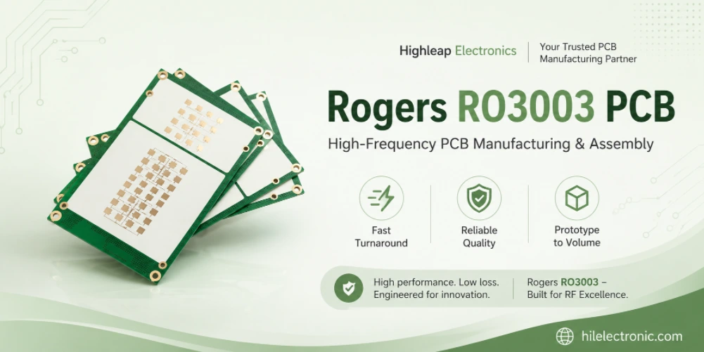
RO3003 PCB manufacturing for radar and mmWave boards depends on dimensional consistency as much as the material specification. When traces, feeds and reference planes become electrically small, the manufacturing tolerance assigned to the finished geometry becomes part of the RF design. A 77 GHz radar board is purchased as a working sensor platform, not as a sheet of RO3003. The customer ultimately cares about antenna alignment, feed-network phase, launch return loss, assembly consistency and radar performance over temperature. That is why a radar PCB supplier must control the full tolerance chain instead of presenting a laminate data table as proof of capability.
Highleap Electronics supports RO3003 radar PCB prototypes and production builds, including thin-core fabrication, antenna registration, PTFE-compatible hole preparation, controlled copper, RFIC assembly and agreed first-article measurements. Highleap Electronics organizes the manufacturing review around the decisions that determine whether a radar prototype can become a repeatable production program.
RO3003 boards for compact RF and radar structures are controlled around the released RF geometry. The fabrication review gives particular attention to dielectric construction, antenna or transmission-line dimensions, drilling and registration so that the manufactured board remains consistent with the design model.
Why RO3003 Is Used in Automotive Radar PCB
RO3003 combines low dielectric loss, controlled dielectric behavior and a glass-free ceramic-filled PTFE construction. These properties are useful in 76–81 GHz radar because antenna and feed-network features are small enough for local material and geometry variation to alter phase, impedance and resonance. The material choice reduces one group of variables, but it does not remove the need to control copper, thickness, artwork and assembly. For vehicle radar applications, radar-specific Rogers PCB requirements should define the antenna and validation constraints around the material choice.
Element length, spacing and alignment to the radome must remain consistent across the production panel.
Phase balance depends on line width, dielectric thickness, copper profile and transition symmetry.
Pad, via and ground geometry can dominate the local return loss even when the laminate is correct.
Material stability must be confirmed together with housing, radome and assembled-module behavior.
The radar tolerance chain
At mmWave frequencies, a dimensional error that looks small on an ordinary PCB can become electrically significant. The production drawing should identify the RF dimensions that control antenna resonance, coupling and phase. It should also establish common datums between the antenna pattern, routed outline, housing features and assembly tooling.
| Variable | Radar impact | Production evidence |
|---|---|---|
| Finished core thickness | Changes impedance, coupling and patch resonance | Incoming material control and cross-section correlation |
| Line width and coupling gap | Moves phase, return loss and array balance | First-article optical measurement |
| Copper roughness | Adds loss and changes effective electrical length | Locked foil construction and supplier traceability |
| Antenna-to-outline registration | Misaligns the array to the radome or cavity | Common datum inspection |
| Mask and finish | Adds dielectric or metal loading | Defined keep-outs and selective finish |
For the system context beyond the laminate, Highleap’s automotive radar PCB and millimeter-wave radar PCB pages cover module architecture, antenna integration and production considerations.
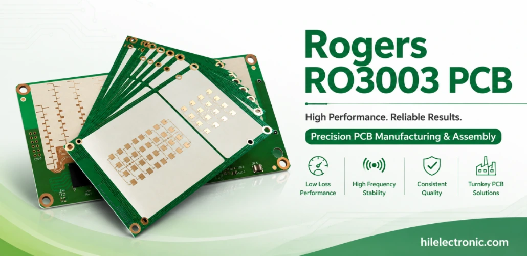
Material scope: the Rogers product name is used to identify the laminate specified for the PCB build. Highleap Electronics provides PCB fabrication and assembly, while the laminate is sourced and verified separately.
Manufacturing Challenges for RO3003 Radar PCB
The fabrication route must preserve the geometry used in the electromagnetic model. This begins with material verification and panel compensation, then continues through imaging, etching, drilling, hole activation, plating, routing and final inspection. Radar yield cannot be inferred from a straight impedance coupon alone because the array and launch may fail while the coupon passes.
Thin cores and copper selection
Thin RO3003 constructions improve compactness and can support tightly coupled structures, but they increase sensitivity to copper thickness, etch profile and handling. The copper foil should be selected before the design is frozen. A smoother foil can reduce conductor loss, while the final plated copper still changes line width and gap. If the model assumes bare copper but production includes finish over a critical feature, the response may shift.
PTFE-compatible drilling and activation
RO3003 requires a fabrication route appropriate for ceramic-filled PTFE. Drill parameters, smear removal or surface activation, hole-wall preparation and plating adhesion must be controlled together. Small radar boards may use few through holes, but every ground via and launch transition still affects current return and shielding. Edge quality also matters where the outline defines antenna spacing or fits a machined housing.
- Confirm the exact laminate thickness and copper code before artwork compensation.
- Mark antenna dimensions and gaps that require finished-feature inspection.
- Define whether solder mask is prohibited over radiators, feeds or tuning features.
- Review via-fence pitch, RFIC ground-via pattern and residual drill tolerance.
- Use routing and inspection datums that match the mechanical housing.
- Include sample retention and lot traceability when radar correlation is required.
High-frequency fabrication also depends on copper and finish decisions. See copper foil and surface finish for high-frequency PCB for the interaction between conductor profile, plating and RF loss.
From RO3003 Prototype PCB to Production
A radar prototype should be treated as a correlation build. The goal is to connect the design model to finished dimensions and assembled RF performance, then decide which controls must remain on every production lot. The first article can include critical-dimension reporting, microsection, impedance or line verification, launch measurements and module-level radar or S-parameter testing supplied by the customer or agreed with the factory.
Material and construction change control
RO3003, RO3003G2 and other radar laminates are not interchangeable without review. A substitution may change Dk, copper construction, dimensional behavior, processing route and available thickness. The approved material designation and supplier revision should remain on the stackup and purchase documentation. If a change is proposed, it should be evaluated against the released model and qualification plan. A move toward RO3003G2 fabrication requirements should be supported by the exact laminate data and an approved construction change.
Radar PCB qualification package
The production release should identify the radar band, critical dimensions, copper construction, finished stackup, surface finish, mask keep-outs, drill and via requirements, outline datums, test coupons and assembly interfaces. For assembled radar modules, the package should also include BOM, placement data, stencil expectations, moisture controls, RFIC handling and inspection limits. Highleap reviews the layer construction, copper definition, via transitions and surface finish with the RF layout. For antenna or mmWave structures, the first article should be compared with the simulated construction rather than judged only by visual inspection. Exact material property values should be checked against the current supplier documentation for the specified grade and construction.
Highleap can coordinate bare-board manufacture with BGA and fine-pitch PCB assembly where the radar IC or processor requires controlled placement and reflow. Prototype, low-volume and repeat production schedules are confirmed after material availability and the qualification scope are reviewed.
Share the RO3003 stackup, antenna artwork, critical tolerances and intended qualification method. Highleap will review the build for thin-core handling, copper, registration, PTFE processing, assembly and repeat-production control.
Radar manufacturing questions
Is RO3003 alone enough to establish 77 GHz system performance? No. Antenna geometry, copper, launch design, assembly and housing remain part of the RF system.
Should the antenna be covered by solder mask? Only if the design model and validation include the exact mask condition. Many radar structures use defined mask keep-outs.
What should be measured on the first article? The answer depends on the design, but critical dimensions, core thickness, registration, launch behavior and assembled RF response are usually more useful than continuity alone. For quotation, include the operating band, stackup, board thickness, copper, controlled-impedance features and RF test method. Those details let the fabricator price the actual precision required for the RO3003 build.

Recommended Posts

TMM4 Filter PCB Manufacturing
TMM4 filter PCB manufacturing is controlled by the...

TMM6 PCB Fabrication
TMM6 fabrication is the process-control page for a mid-Dk...

TMM3 PCB Manufacturing for RF Modules
TMM3 PCB manufacturing is most useful where the RF module...

TMM10 PCB Manufacturing for Compact RF Designs
Table of contentsHow TMM10 Shrinks RF StructuresTMM10 vs...
How to get a quote for PCBs
Let’s run DFM/DFA analysis for you and get back to you with a report. You can upload your files securely through our website. We require the following information in order to give you a quote:
-
- Gerber, ODB++, or .pcb, spec.
- BOM list if you require assembly
- Quantity
- Turn time
For PCBA services, please provide your BOM (Bill of Materials) and any specific assembly instructions. We also offer DFM/DFA analysis to optimize your designs for manufacturability and assembly, ensuring a smooth production process.