
TMM Microwave PCB Manufacturing
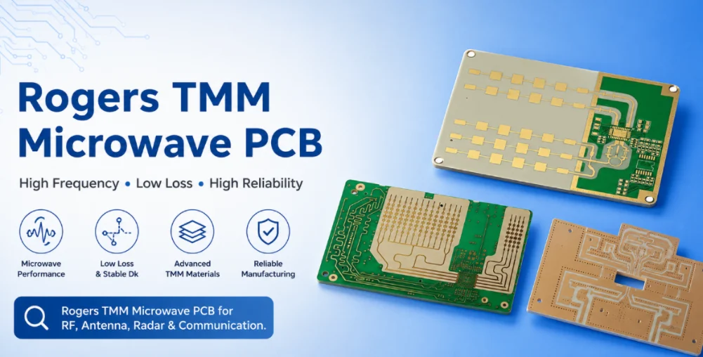
Table of Contents
- Rogers TMM Microwave PCB Manufacturing for High-Frequency Circuits
- Rogers TMM Microwave Material Selection by Circuit Function
- Microwave PCB Insertion-Loss Budget on Rogers TMM
- Microstrip, Stripline and GCPW Structures for Rogers TMM Microwave PCB
- Rogers TMM Microwave Filter and Coupler PCB Design
- Rogers TMM Power Amplifier PCB Layout and Thermal Design
- Microwave Connector Launches, Via Transitions and Grounding
- Manufacturing Controls for Rogers TMM Microwave PCB
- Microwave PCB Quote Checklist for Rogers TMM Builds
TMM microwave PCB manufacturing is most sensitive where the circuit geometry carries the function, such as filters, couplers and RF amplifiers. Small changes in line width, spacing or reference-plane distance can change the tuned response even when the material grade is correct. A Rogers TMM microwave PCB is a high-frequency circuit board built on Rogers TMM thermoset microwave laminate for filters, couplers, resonators, power amplifiers, low-noise amplifiers, radar modules, satellite communication hardware and precision microwave assemblies. At microwave frequencies, the PCB substrate, copper profile, surface finish, via transitions and grounding are part of the circuit. The practical task is to select the TMM grade, control loss, fabricate the stackup and quote the board without losing the simulated RF response.
The microwave page focuses on the geometry of filters, amplifiers and couplers. The manufacturing discussion connects dielectric construction, conductor dimensions, plated transitions and inspection with the RF structures that determine the finished circuit response.
Rogers TMM Microwave PCB Manufacturing for High-Frequency Circuits
Why is microwave PCB manufacturing more sensitive than general RF PCB manufacturing?
Microwave circuits operate where physical dimensions become a large fraction of wavelength. A short via stub, connector pad, copper finish, bend, gap or plated edge can change return loss and insertion loss. A filter can shift center frequency. A coupler can miss coupling flatness. A power amplifier can become unstable if the ground path is not low inductance. The manufacturer therefore needs to preserve the geometry and stackup assumed by the electromagnetic model.
Which microwave circuits are commonly built on Rogers TMM?
Typical circuits include microstrip filters, interdigital and hairpin filters, branch-line couplers, directional couplers, Wilkinson dividers, hybrid couplers, low-noise amplifier boards, power amplifier boards, impedance transformers, resonators, oscillator boards, radar front-end boards and satellite communication modules. TMM is selected when these circuits need stable Dk, low loss, good thermal behavior, rigid handling and reliable plated through holes.
Where does Rogers TMM fit compared with PTFE and RO4350B?
Pure PTFE laminates can offer lower dielectric loss, but they are softer and often require more specialized processing. RO4350B is cost-effective and widely used for mainstream RF, but it has different Dk, loss, CTE and grade range. TMM sits in a useful middle position: low loss, rigid thermoset behavior, high-Dk options and controlled thermal-expansion behavior. It is not automatically the cheapest or lowest-loss material; it is chosen when the full electrical, mechanical and manufacturing balance fits the product.
Rogers TMM Microwave Material Selection by Circuit Function
Microwave material selection starts with circuit function, not with a single Dk number. A wideband transition or feed may prefer lower Dk. A compact resonator may need high Dk. A thermally exposed filter may prioritize temperature stability. A power amplifier may need thermal conductivity and reliable grounding. The table below connects the TMM grades to typical microwave uses.
| Rogers TMM grade | Process Dk @ 10 GHz | Published design Dk | Df @ 10 GHz | TCDk, ppm/°C | Typical design use |
|---|---|---|---|---|---|
| TMM3 | 3.27 ± 0.032 | 3.45 | 0.0020 | +37 | Lower-Dk RF lines, wider 50 Ω traces, broadband feeds, antenna structures and transitions. |
| TMM4 | 4.50 ± 0.045 | 4.70 | 0.0020 | +15 | Medium-Dk RF and microwave circuits where modest size reduction is useful. |
| TMM6 | 6.00 ± 0.080 | 6.30 | 0.0023 | −11 | Compact microwave layouts, filters, matching sections and moderate-size-reduction designs. |
| TMM10 | 9.20 ± 0.230 | 9.80 | 0.0022 | −38 | High-Dk miniaturized filters, couplers, resonators and alumina-replacement evaluations. |
| TMM10i | 9.80 ± 0.245 | 9.90 | 0.0020 | −43 | High-Dk circuits needing more isotropic dielectric behavior and stable compact geometry. |
| TMM13i | 12.85 ± 0.35 | 12.20 | 0.0019 | −70 | Very compact high-Dk resonators, antenna components, dielectric structures and specialty RF modules. |
Which TMM grade is best for microwave filters?
For compact filters and resonators, TMM6, TMM10, TMM10i and TMM13i are often reviewed because higher Dk reduces resonator size. For wider-band filters or structures that need wider lines and less tolerance sensitivity, TMM3 or TMM4 may be better. The correct choice depends on center frequency, bandwidth, unloaded Q, layout area, coupling gaps, manufacturing tolerance and expected temperature range.
Which TMM grade is best for microwave power amplifiers?
Power amplifier boards usually prioritize stable impedance, heat spreading, low-inductance grounding and assembly reliability. TMM3, TMM4 or TMM6 are common candidates when line widths must remain practical and broadband matching is required. High-Dk TMM can be used for compact matching or special module geometry, but the narrower lines and increased field concentration should be reviewed carefully.
Microwave PCB Insertion-Loss Budget on Rogers TMM
What contributes to insertion loss on a TMM microwave PCB?
Insertion loss is the sum of dielectric loss, conductor loss, radiation/leakage loss and discontinuity loss. Dielectric loss comes from the TMM dissipation factor and grows with frequency and line length. Conductor loss comes from copper roughness, copper thickness, surface finish and trace width. Radiation loss comes from open structures, poor shielding and discontinuities. Discontinuity loss comes from launches, bends, vias, tapers, pads and reference-plane changes.
Why can conductor loss dominate even with low-loss TMM?
At microwave frequencies, current flows near the conductor surface. Rough copper increases the effective path length, and nickel-bearing finishes can add extra resistance. A narrow high-Dk line can have more conductor loss than a wider lower-Dk line, even if both use the same laminate family. This is why a microwave PCB review should include copper foil and surface finish, not only Dk and Df.
How should loss be validated?
For a prototype, include an insertion-loss coupon that uses the same line type, copper, finish and dielectric as the product circuit. Measure it with the intended connectors and de-embedding plan if required. If measured loss is higher than expected, separate the causes: dielectric loss, conductor roughness, finish penalty, launch return loss, via transition loss or radiation. A structured measurement prevents unnecessary material changes.
| Loss source | Main driver | Manufacturing lever | Validation method |
|---|---|---|---|
| Dielectric loss | Df, frequency and length | Grade choice and shorter routing | Modeled line and loss coupon |
| Conductor loss | Copper roughness, finish, width | Low-profile copper, finish selection, manufacturable widths | Coupon with production finish |
| Discontinuity loss | Launches, vias, pads, bends | EM review, backdrill where justified, reference continuity | S-parameter measurement |
| Radiation loss | Open structures and poor shielding | Stripline, GCPW, via fences, enclosure planning | Near-field scan or comparison coupons |
Material scope: This article addresses microwave-PCB fabrication when the design specifies TMM laminate. Confirm the approved grade, construction and material documentation in the RFQ.
Microstrip, Stripline and GCPW Structures for Rogers TMM Microwave PCB
When is microstrip acceptable for microwave circuits?
Microstrip is acceptable when access, tuning and component mounting are important and radiation can be controlled. It is common in filters, matching networks and couplers. At higher frequencies, microstrip discontinuities must be modeled. Solder mask, plating thickness and nearby metal housings should not be ignored because they alter the field environment.
When should stripline be used for microwave isolation?
Stripline is useful when the circuit needs shielding from other board areas or the enclosure. It reduces radiation and can improve crosstalk control. The trade-off is more complex fabrication and less access for tuning. Stripline also puts more responsibility on lamination thickness and registration, because the line is buried and cannot be adjusted after fabrication.
Why is GCPW common in microwave modules?
GCPW provides field confinement on an outer layer while keeping components accessible. It is widely used for connector launches, dense modules and mmWave transitions. The side-ground gap, via fence and ground continuity are critical. A missing or inconsistent via fence can create resonances and degrade return loss.
Rogers TMM Microwave Filter and Coupler PCB Design
Why are microwave filters sensitive to TMM Dk and etch tolerance?
Filter frequency response depends on resonator length, coupling gap, dielectric constant and conductor loss. If the actual Dk is different from the modeled value, the center frequency shifts. If gaps etch too wide or too narrow, bandwidth and ripple change. If copper or finish loss is too high, insertion loss increases and Q drops. TMM helps by offering controlled Dk, but the final response still depends on manufacturing discipline.
How should coupled-line gaps be handled in fabrication?
Coupled-line filters and couplers often use narrow gaps. These gaps should be identified as critical dimensions on the drawing. The manufacturer should review minimum gap capability, etch compensation and inspection method. If the gap is near the fabrication limit, the designer may need to adjust dielectric thickness, Dk or topology rather than force a fragile geometry into production.
Can TMM replace alumina in some microwave modules?
Rogers positions TMM10 and TMM10i as candidates for replacing alumina substrates in some applications. The reason is the combination of high Dk, rigid thermoset behavior and PCB-like processing. This is not a universal substitution: alumina still has very high thermal conductivity and ceramic-specific advantages. TMM is reviewed when a design wants compact high-Dk behavior with PCB manufacturing, plated holes and easier board integration.
Rogers TMM Power Amplifier PCB Layout and Thermal Design
What matters most in a TMM power amplifier PCB?
Power amplifier boards need controlled input/output impedance, low-inductance grounding, thermal spreading, stable bias routing and reliable assembly. The RF matching network must be close to the device and built on the intended dielectric. Ground vias under and around the package should be dense enough to reduce inductance and support heat flow. Copper area, thermal vias and mounting strategy should match the device datasheet and system heat path.
How does TMM help with thermal stability?
TMM has low thermal coefficient of dielectric constant and better thermal conductivity than many traditional PTFE-based laminates. As the board warms, electrical length and matching remain more stable than with materials whose Dk changes more strongly. Temperature behavior is especially important for amplifiers, oscillators and filters that operate over wide environmental ranges. More detail is covered on the Rogers TMM temperature-stable PCB page.
What manufacturing mistakes affect PA stability?
Common mistakes include sparse ground vias, long decoupling loops, uncontrolled launch geometry, solder-mask intrusion on RF lines, unsuitable finish, poor thermal via plating and changes to dielectric thickness after simulation. These problems can reduce gain, increase loss, create oscillation or cause thermal reliability issues.
Microwave Connector Launches, Via Transitions and Grounding
Why do connector launches need special review?
The connector launch is a transition between coaxial mode and PCB transmission-line mode. Pad size, ground via placement, reference plane clearance, solder volume and finish all affect return loss. A launch that works at 2 GHz may not be acceptable at 18 GHz or 40 GHz. The launch should be modeled or based on a proven footprint for the selected connector and TMM stackup.
When is backdrilling necessary?
Backdrilling removes unused via stubs that can resonate and degrade microwave performance. It should be applied when the via stub length is electrically significant for the operating band and when the mechanical stackup allows it. Backdrilling adds cost and tolerance requirements, so it should be specified for real performance need rather than as a default.
How should grounding be designed?
Microwave grounding requires short current loops, continuous reference planes, via stitching around GCPW, strong ground around connectors and low-inductance device grounds. Ground is part of the circuit, not a fill pattern added after routing. Poor grounding shows up as return loss, crosstalk, gain ripple, PA instability or radiation.
Manufacturing Controls for Rogers TMM Microwave PCBs
Fabrication Drawing Requirements
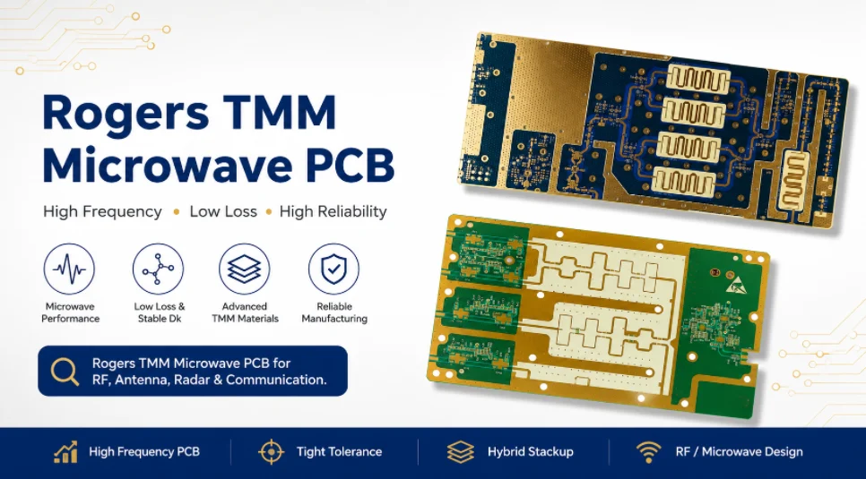
The fabrication drawing should define the items that directly affect RF performance, manufacturability and inspection. Key requirements include Rogers TMM grade, dielectric thickness, layer stackup, finished board thickness, copper weight, surface finish, solder mask restrictions, controlled impedance, critical dimensions, acceptance class, test requirements and coupon requirements. Highleap reviews the microwave layer construction, vias, copper definition and any tuned dimensions before fabrication. First-article validation should match the circuit type, with RF measurement used where the production release depends on measured performance. Exact material property values should be checked against the current supplier documentation for the specified grade and construction.
For microwave filters, couplers and resonators, critical resonator lengths, coupling gaps and ground clearances should be clearly marked. For antenna boards, patch dimensions, feed geometry, edge clearance and solder mask keepout should be specified. For power amplifier boards, thermal via arrays, exposed copper, grounding pads and heat-spreading areas should be defined. For connector launches, the drawing should show connector type, launch footprint, reference-plane condition and ground-via pattern.
Vague notes such as “high frequency material” or “standard finish” can create quotation and production risks. A Rogers TMM microwave PCB drawing should use measurable requirements so that engineering, CAM, fabrication and inspection teams follow the same build conditions.
Prototype Data for Production Control
Prototype results should be converted into controlled production revisions. If insertion loss is higher than expected, copper profile, surface finish, finished trace width, solder mask condition and connector launch loss should be reviewed before changing the Rogers TMM grade. If frequency shifts, the review should focus on dielectric thickness, design Dk assumptions, etched length, coupling gap and board thickness. If return loss is poor, launch geometry, via transitions, ground-via placement and reference-plane continuity should be checked.
After the cause is confirmed, the production package should be updated with revised Gerbers, approved stackup, measured impedance data and corrected fabrication notes. Repeat orders should follow the same controlled revision, not informal prototype comments. The prototype-to-production workflow is explained in the Rogers TMM PCB prototype guide.
Microwave PCB Quote Checklist for Rogers TMM Builds
Engineering Data Required for an Accurate Quote
A Rogers TMM microwave PCB quote should be based on complete engineering data, not only board size and layer count. The RFQ should clearly show the RF function, material requirement, stackup, manufacturing files, impedance targets, finish requirement, test plan, quantity and assembly needs.
- Operating frequency range and RF function, such as antenna, filter, coupler, power amplifier, feed network or test fixture.
- Gerber, ODB++ or IPC-2581 files, drill data and fabrication drawing.
- Rogers TMM grade, dielectric thickness and finished board thickness.
- Layer stackup, copper weight, reference planes and bond material for hybrid builds.
- Transmission-line type, such as microstrip, stripline or grounded coplanar waveguide.
- Controlled-impedance targets, tolerances and coupon requirements.
- Critical dimensions for filters, couplers, resonators, antenna areas and connector launches.
- Surface finish, copper profile preference and solder mask restrictions.
- Via requirements, including RF grounding vias, via fences and thermal via arrays.
- Testing and documentation requirements, such as impedance report, microsection, material certificate or certificate of conformance.
- Quantity, delivery target, prototype or production status and PCBA requirements if assembly support is needed.
Price and Schedule Factors
The final quotation depends on Rogers TMM grade, material availability, dielectric thickness, panel utilization, layer count, hybrid construction, copper profile, surface finish, drilling complexity, via density, impedance testing, coupon requirements, documentation level, order quantity and lead time.
To avoid price changes after review, the RFQ should separate fixed requirements from flexible options. If the Rogers TMM grade, surface finish, impedance report or microsection is mandatory, it should be stated before quotation. For cost planning and quotation variables, see the Rogers TMM PCB price guide. For quotation, provide the microwave topology or critical dimensions, stackup, frequency band, finish and quantity. A supplier can then judge the machining, inspection and RF verification scope from the real design.

Recommended Posts

TMM4 Filter PCB Manufacturing
TMM4 filter PCB manufacturing is controlled by the...

TMM3 PCB Manufacturing for RF Modules
TMM3 PCB manufacturing is most useful where the RF module...

TMM6 PCB Fabrication
TMM6 fabrication is the process-control page for a mid-Dk...

TMM10 PCB Manufacturing for Compact RF Designs
Table of contentsHow TMM10 Shrinks RF StructuresTMM10 vs...
How to get a quote for PCBs
Let’s run DFM/DFA analysis for you and get back to you with a report. You can upload your files securely through our website. We require the following information in order to give you a quote:
-
- Gerber, ODB++, or .pcb, spec.
- BOM list if you require assembly
- Quantity
- Turn time
For PCBA services, please provide your BOM (Bill of Materials) and any specific assembly instructions. We also offer DFM/DFA analysis to optimize your designs for manufacturability and assembly, ensuring a smooth production process.