
SPDT Switch: A Comprehensive Guide

In the field of electronics, switches play an integral role in controlling circuits, managing signal flow, and toggling power. One such switch, the SPDT switch (Single Pole Double Throw switch), stands out for its versatility and widespread use in various applications. Whether you’re working with simple household devices or complex industrial systems, understanding how an SPDT switch works, how to wire it, and where it’s applied is crucial.
When an SPDT switch is selected for a real product, the footprint, contact rating, and soldering method should be checked during PCB layout planning and confirmed against the final board assembly process so the switch does not become a field reliability problem.
This article provides a comprehensive look at SPDT switches, delving into their functionality, structure, wiring techniques, and practical applications. We’ll also explore common mistakes in wiring and offer troubleshooting tips for ensuring a seamless operation.
What Is an SPDT Switch?
An SPDT switch is a type of electrical switch that has one input terminal and two output terminals. The unique feature of an SPDT switch is its ability to toggle between two output terminals, effectively connecting the input to one output at a time. This makes it different from other switch types, like the SPST (Single Pole Single Throw), which only connects or disconnects one circuit.
An SPDT switch is designed to control the flow of electricity between the input terminal and either of the output terminals. The user manually operates the switch to toggle the connection between these terminals, enabling the redirection of current in a circuit.
Components of an SPDT Switch:
- Common Terminal (C): This is the input terminal where the power source or signal enters.
- Normally Open (NO) Terminal: When the switch is activated, the common terminal connects to this output terminal, allowing current or signals to pass through.
- Normally Closed (NC) Terminal: This terminal is connected to the common terminal when the switch is in its resting state (OFF position). When the switch is toggled, the connection between the common and NC terminals is broken, and the current is redirected to the NO terminal.
How Does an SPDT Switch Work?
The SPDT switch operates by shifting the connection between its common terminal (input) and the two output terminals (NO and NC). The switch physically moves an internal contact point (or lever) between the two outputs.
When the switch is in its OFF position, the common terminal is connected to the NC terminal, allowing the signal or current to pass through this output. When the switch is flipped to the ON position, the common terminal disconnects from the NC terminal and instead connects to the NO terminal, effectively switching the output path of the signal.
This mechanism makes the SPDT switch particularly useful in applications where you need to choose between two circuits or signal paths, without disconnecting the input source entirely.
Common Uses of SPDT Switches
SPDT switches are essential components in many electrical and electronic systems, ranging from household devices to complex industrial machines. Below are some common applications that showcase their versatility:
Reversing DC Motor Directions
One of the most well-known uses of an SPDT switch is to reverse the direction of a DC motor. By wiring an SPDT switch in such a way that it changes the polarity of the power supplied to the motor, the motor can be made to spin clockwise or counterclockwise. This setup is commonly found in:
- Electric fans
- Robotics
- Conveyor systems
To reverse the motor’s direction, the SPDT switch toggles the polarity of the DC voltage applied to the motor’s terminals.
Selector Switches for Audio Systems
In audio equipment, such as electric guitars, SPDT switches are often used as pickup selectors. This allows the musician to toggle between different pickups (for example, bridge or neck pickups) to produce different tonal qualities. The versatility of SPDT switches in audio systems doesn’t end with guitars. They are also used in mixing boards to switch between different audio channels and in amplifiers to control signal paths.
Control Circuits in Industrial Systems
In industrial environments, SPDT switches are often employed to control relays, alarms, and other critical components. For example, the switch can activate one machine while turning off another, ensuring smooth operation across multiple devices. Additionally, SPDT switches can serve as part of safety circuits that automatically cut power or activate emergency systems in hazardous conditions.
Safety and Power Supply Control
SPDT switches are ideal for controlling power supplies in various applications. By toggling between different voltage levels or switching power sources, an SPDT switch helps ensure the correct operation of machinery, systems, or safety controls. In industrial settings, they are commonly used in emergency shutdown procedures where a switch is needed to divert power away from critical equipment.
Multi-Circuit Control
In complex systems, SPDT switches can control multiple circuits simultaneously by switching between different output connections. This setup allows for flexible control of different devices or systems with just one input, reducing the complexity of wiring multiple switches. For example, a switch can control which circuit gets powered in a multi-device setup, turning off one while activating another.

Internal Components of an SPDT Switch
Understanding the internal components of an SPDT switch is crucial to fully appreciate how this versatile device operates. Each component plays a unique role in ensuring that the switch effectively alternates between two output terminals (NO and NC). Below is an expanded breakdown of the key components and how they work in tandem.
1. Common Terminal (Input)
The common terminal, often labeled as “C” or simply “COM,” serves as the entry point for the electrical current or signal. It is connected to the power source or the input signal, such as a voltage supply or data line. This terminal remains constantly connected to the input, and it acts as the central hub from which the current or signal is routed to one of the two output terminals — either Normally Open (NO) or Normally Closed (NC).
- Function: The common terminal does not determine whether a circuit is open or closed on its own. Its primary role is to connect to either the NO or NC terminal based on the position of the switch, thereby controlling the flow of current or signal. It is the anchor point for the switch’s operation, alternating between outputs based on the user’s input.
2. Normally Open (NO) Terminal
The Normally Open (NO) terminal is an output terminal that remains disconnected in the switch’s default or “off” position. The term “Normally Open” refers to the fact that, in the resting state of the switch, the circuit path from the common terminal to the NO terminal is incomplete, meaning no current or signal flows through.
- Function: When the user activates the switch by toggling it, the movable contact inside the switch connects the common terminal to the NO terminal. This allows current or signals to flow from the common terminal to the NO terminal, completing the circuit and powering any device connected to this terminal. For example, in a simple circuit with an SPDT switch controlling two devices, flipping the switch to the ON position would activate the device connected to the NO terminal.
3. Normally Closed (NC) Terminal
The Normally Closed (NC) terminal, as its name suggests, is the output terminal that remains connected to the common terminal when the switch is in its default or “off” position. In this state, the circuit path between the common terminal and the NC terminal is complete, allowing current or signal to flow without any manual intervention.
- Function: When the switch is not engaged (in its resting state), the NC terminal is connected to the common terminal, ensuring that current flows from the input to the NC output. This provides a default or “fail-safe” path for the signal or current. In many applications, this terminal is used to keep a device powered by default, and it is deactivated when the switch is toggled.
For example, in systems where constant operation is required, like in a safety alarm or a power indicator, the NC terminal keeps the circuit closed and active until the switch is flipped to interrupt the flow.
4. Movable Contact (Lever or Arm)
At the heart of the SPDT switch’s internal mechanism is the movable contact. This is the critical component that physically shifts between the NO and NC terminals, thereby controlling which output terminal the common terminal is connected to. The movable contact is typically a conductive lever, arm, or strip made from metal, such as copper or brass, which offers excellent conductivity.
- Function: The movable contact is directly responsible for closing or opening the circuit paths between the common terminal and the NO or NC terminals. When the switch’s actuator (such as a toggle or button) is manipulated, it moves the contact between the NO and NC terminals. This physical movement is what allows the switch to alternate the electrical connection between the terminals, either energizing a device (connected to the NO terminal) or keeping another device on standby (connected to the NC terminal).
The movement of this contact is often supported by a pivot mechanism, allowing smooth transitions between the NO and NC terminals. In high-quality switches, the contact is designed to move quickly and snap securely into place, minimizing arcing and wear on the contact points.
5. Actuator
The actuator is the external part of the switch that the user interacts with to control the internal movable contact. Depending on the design of the SPDT switch, the actuator may be a toggle switch, push-button, rotary knob, or slider. Each type of actuator provides a different method of operation, but they all perform the same essential function — moving the internal contact between the NO and NC terminals.
- Function: The actuator is the user interface of the switch. When it is toggled or pushed, it transmits mechanical force to the internal movable contact, causing the contact to shift its position. For example, in a toggle switch, flipping the lever up or down physically moves the internal contact to engage either the NO or NC terminal. Similarly, a push-button actuator may allow the switch to change states with each press, moving the contact from NO to NC or vice versa.
Actuators often incorporate mechanical feedback, such as a “click” sound or physical resistance, to signal that the switch has been successfully activated, giving users confidence that the switch has changed positions.
6. Spring Mechanism
Many SPDT switches incorporate a spring mechanism that plays a critical role in ensuring reliable switching action and maintaining the default state of the switch. This spring mechanism is typically designed to either snap the internal contact into place when the switch is toggled or return the switch to a default position (such as in momentary switches).
- Function: The spring mechanism provides tension and stability to the movable contact, ensuring that it remains securely in place once switched. For instance, when you flip a toggle switch, the spring provides the necessary force to move the internal contact and snap it into position, securely connecting the common terminal to either the NO or NC terminal. This snap action minimizes electrical arcing (sparking) between the contacts, which could otherwise occur as the switch toggles between terminals.
In momentary switches, the spring mechanism ensures the switch returns to its default state after the user releases it. For example, a push-button SPDT switch might automatically return to the NC position after being pressed due to the action of the spring.

Wiring an SPDT Switch
Wiring an SPDT switch can be done in several configurations depending on the application. Here’s a general guide to wiring an SPDT switch for basic and advanced uses:
Basic SPDT Switch Wiring (Single Circuit Control)
- Identify the Terminals: Start by identifying the three terminals: Common (C), Normally Open (NO), and Normally Closed (NC).
- Connect the Input Source: Wire the input power or signal source to the common terminal. This is typically the terminal that will always receive power or a signal.
- Wire the NO Terminal: Connect the NO terminal to the first output device, such as a motor or light. When the switch is toggled ON, this device will be activated.
- Wire the NC Terminal: Connect the NC terminal to the second output or another ground connection. When the switch is in the OFF position, this output is engaged.
- Test the Circuit: Once wired, use a multimeter to ensure proper connectivity and functionality. Flip the switch to see the current move between the NO and NC terminals as expected.
Advanced SPDT Switch Wiring (Multiple Circuit Control)
In more complex applications, an SPDT switch can be wired to control multiple circuits or devices. Here’s how:
- Identify Circuits: Start by identifying the circuits you wish to control with the SPDT switch. Each circuit should have a unique input and output.
- Common Connection: Connect the common terminal to the shared input, which might be the positive side of a power supply.
- Wiring Multiple Outputs: Connect each output circuit to either the NO or NC terminal. This way, the switch will toggle power between these two circuits.
- Testing and Safety: After wiring, test the circuit by toggling the switch and checking each circuit’s functionality. Ensure that your connections are secure, and the switch is properly rated for your power supply.
Troubleshooting SPDT Switch Wiring Issues
When an SPDT switch fails to work as expected, diagnosing the issue involves a systematic approach:
1. Check for Proper Wiring
Ensure that the common, NO, and NC terminals are correctly wired. Miswiring these terminals is a common mistake that can cause the switch to fail to direct current to the appropriate output.
2. Use a Multimeter
A multimeter can help you check for continuity between the terminals. When the switch is in one position, the common terminal should have continuity with either the NO or NC terminal. If there is no continuity, the switch may be faulty.
3. Inspect for Short Circuits
Check for exposed wires or connections that may have shorted the circuit. Shorts can lead to unpredictable behavior or even damage the switch and connected devices.
4. Test Voltage Levels
Ensure that the voltage and current passing through the switch match its rated capacity. If the voltage exceeds the switch’s rating, it may not function properly or could be damaged over time.
5. Switch Replacement
If all wiring and voltage checks out but the switch still malfunctions, consider replacing the SPDT switch. Switches can wear out over time, especially in high-usage applications.

Common Mistakes to Avoid When Wiring SPDT Switches
There are several common mistakes that can occur when working with SPDT switches:
1. Miswiring the NO and NC Terminals
As mentioned earlier, incorrectly wiring the NO and NC terminals is a frequent error. Always refer to the manufacturer’s diagram to ensure the terminals are correctly connected to the appropriate circuits.
2. Loose Connections
Loose or poorly connected wires can lead to intermittent connectivity or short circuits. Make sure that all wires are securely fastened, either by soldering or using wire connectors.
3. Using Inadequate Wire Gauge
Ensure that the wires used to connect the switch are of an appropriate gauge for the current being carried. Thin wires may overheat and degrade, leading to electrical hazards.
4. Ignoring Voltage and Current Ratings
Each SPDT switch is rated for a specific voltage and current range. Exceeding these limits can result in the switch overheating, failing, or even causing damage to other components in the circuit.
5. Failing to Test the Circuit Before Use
After wiring the switch, it’s essential to test the circuit with a multimeter or testing equipment before connecting it to expensive or sensitive components. This ensures that any wiring errors or issues are identified early.
Safety Considerations
Working with electrical switches like the SPDT switch requires careful attention to safety. Here are some key safety precautions:
- Always Turn Off the Power: Before wiring or making adjustments to a circuit, ensure the power is completely turned off.
- Use Insulated Tools: Always use tools with proper insulation to minimize the risk of electrical shock.
- Double-Check Connections: After wiring, double-check all connections to make sure no exposed wires could lead to a short circuit.
- Wear Protective Gear: In more complex systems, wearing gloves and protective eyewear can reduce the risk of injury from electrical faults.
Conclusion
The SPDT switch is a highly versatile component that plays a vital role in controlling circuits, signals, and devices in both simple and complex systems. Its ability to toggle between two outputs from a single input makes it invaluable in various applications, from reversing motors to switching between power sources.
Understanding the internal workings of an SPDT switch, how to wire it correctly, and how to troubleshoot common issues are key skills for anyone working in electronics or electrical systems. By following proper wiring techniques, adhering to safety precautions, and using troubleshooting methods, you can ensure that your SPDT switch operates efficiently and reliably.
Whether you’re working on a simple DIY project or a more complex industrial system, mastering the use of SPDT switches will provide you with greater control over your electrical designs and help you achieve the desired results with precision and safety.

Recommended Posts
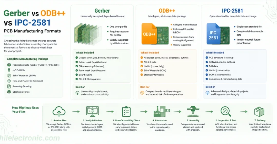
Gerber vs ODB++ vs IPC-2581: Choosing a PCB Manufacturing Data Package
Figure 1. Gerber vs ODB++ vs IPC-2581 image for Highleap...
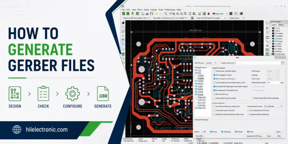
How to Generate Gerber Files for PCB Manufacturing
Figure 1. how to generate Gerber files image for Highleap...
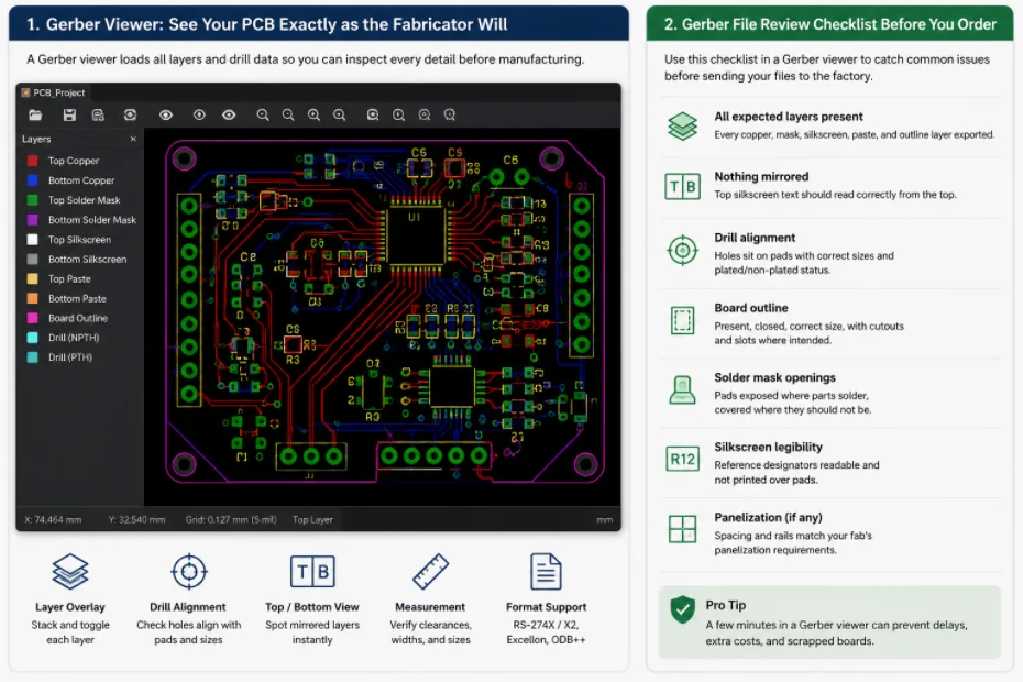
Gerber File Review Checklist: How to Check PCB Files Before You Order
Figure 1. Gerber file review catches missing layers, drill...
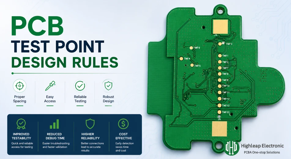
PCB Test Point Design Rules for Debug and ICT
Figure 1. PCB test point design rules help make debugging,...