
Leading PCB and PCBA Manufacturer for USB Expanders

Figure 1. A comprehensive application chart for USB expanders and adapters, detailing typical connectivity scenarios for universal devices. Custom PCB and PCBA assembly solutions for various USB expanders including USB-C adapters, multi-port splitters, and industrial connectivity modules.
A USB expander adds more ports and more port types to a computer that doesn’t have enough. Modern laptops ship with one or two USB-C ports and nothing else — no USB-A, no HDMI, no Ethernet, no SD card slot. A USB expander solves this by splitting one USB connection into multiple downstream ports, often mixing USB-A, USB-C, HDMI, Ethernet, and card readers in a single device. This guide covers the product categories, key components, PCB design considerations, and manufacturing requirements for USB expander hardware.
Table of Contents
- What a USB Expander Actually Does
- USB-A Port Expanders: Adding More USB Ports
- USB-C Multi-Function Expanders: Ports Plus Conversion
- Powered USB Expanders and Charging Stations
- Industrial and Embedded USB Expanders
- PCB Design Essentials for USB Expanders
- USB Expander Manufacturing at Highleap
1. What a USB Expander Actually Does
A USB expander takes one USB port on a host computer and turns it into multiple ports. The simplest version is a 4-port USB-A hub — one cable to the PC, four USB-A ports for peripherals. The most advanced version is a USB-C docking station that provides USB-A, USB-C, HDMI, DisplayPort, Gigabit Ethernet, audio, and SD card slots from a single USB-C connection, while also charging the laptop through USB Power Delivery.
Three scenarios drive almost all USB expander sales:
Not enough ports. A laptop with two USB-C ports cannot simultaneously connect a mouse, keyboard, external drive, webcam, and phone charger. A USB expander adds the missing ports. This is the most common consumer use case and the highest-volume product category.
Wrong port types. A USB-C-only laptop cannot directly connect USB-A peripherals, an HDMI monitor, or an Ethernet cable. A USB expander with mixed port types bridges the gap — it acts as both a port multiplier and an interface converter in one device.
Desktop convenience. A desktop PC tower under a desk has USB ports on the back panel that are hard to reach. A USB expander sitting on the desk surface, connected to the PC with a single cable, puts all the ports within arm’s reach. This is a large market segment for 4-port and 7-port desktop hubs.
| USB Expander Type | Typical Ports | Power Source | Primary Use | Retail Price Range |
|---|---|---|---|---|
| Basic USB-A hub | 4× USB-A | Bus-powered | Add USB-A ports to any PC | $8–25 |
| Powered USB-A hub | 4–10× USB-A | External DC adapter | Desktop workstation, charging | $20–80 |
| USB-C multi-port adapter | USB-A + HDMI + ETH + SD | Bus-powered or PD pass-through | Laptop expansion, travel | $25–80 |
| USB-C docking station | USB + dual video + ETH + audio + PD | External power + PD pass-through | Full desk replacement | $80–300 |
| Industrial USB expander | 4–16× USB-A | DIN-rail 12/24 V DC | Factory, kiosk, signage | $150–800 |
At the core of every USB expander is a USB hub IC — a chip that implements the USB hub specification, managing enumeration, bandwidth allocation, and power distribution across all downstream ports. Different port types (HDMI, Ethernet, audio) require additional bridge ICs on the same PCB. The PCB design and component selection determine the product’s performance, reliability, and cost.
2. USB-A Port Expanders: Adding More USB Ports
The simplest and highest-volume USB expander category. One USB cable to the host, multiple USB-A ports for peripherals. No protocol conversion — the expander is purely a USB hub.
Bus-powered 4-port USB 3.0 hub. The entry-level product. A single hub IC (VIA VL817, Genesys Logic GL3520, or similar) drives four USB-A downstream ports. Bus-powered means the hub draws all its power from the host USB port — no external adapter needed. The trade-off: total available current is limited to 900 mA (USB 3.0 spec), shared across the hub overhead and all four ports. This is enough for mice, keyboards, flash drives, and card readers, but not enough for external hard drives or phone charging. PCB: 2–4 layer, approximately 60 × 30 mm. BOM at volume: $3–6.
7-port and 10-port hubs. For users who connect many peripherals — video editors, audio producers, developers with multiple test devices. The internal architecture cascades two or three 4-port hub ICs. Always self-powered (external adapter) because bus power cannot supply this many ports. Per-port power switches and LED indicators are the features that separate premium products (Anker, Sabrent, UGREEN) from generic alternatives. BOM at volume: $8–15.
USB 2.0 vs USB 3.0 hubs. USB 2.0 hubs (480 Mbps shared bandwidth) use simpler, cheaper ICs and 2-layer PCBs. USB 3.0 hubs (5 Gbps) require controlled-impedance differential pairs, tighter PCB layout rules, and 4-layer boards. USB 3.0 hubs also maintain backward-compatible USB 2.0 data paths in parallel — the hub IC manages both simultaneously. For applications that only need HID devices (keyboards, mice, barcode scanners), a USB 2.0 hub is the cost-optimal choice.
USB-C upstream, USB-A downstream. A growing product segment that addresses the “dongle problem”: the laptop only has USB-C, but all existing peripherals have USB-A. The hub connects to the laptop via USB-C and presents USB-A ports for legacy devices. The PCB adds USB-C CC (Configuration Channel) pin management on the upstream port, which requires additional circuitry compared to a USB-A upstream design.

Figure 2. USB Expanders
3. USB-C Multi-Function Expanders: Ports Plus Conversion
This is the fastest-growing USB expander category. A single USB-C cable from the laptop provides USB data ports, video output, network connectivity, and sometimes power delivery — combining port expansion and interface conversion in one compact device.
5-in-1 and 7-in-1 USB-C adapters. The popular travel and office product. Typical configuration: 2× USB-A, 1× HDMI (4K@30 Hz or 4K@60 Hz), 1× SD card reader, 1× USB-C PD pass-through for laptop charging. Bus-powered from the USB-C host. The PCB carries a USB hub IC for the data ports, plus a DisplayPort-to-HDMI converter IC (Parade PS176, Lontium LT8711, or similar) for video output. PCB: 4–6 layer with HDI PCB construction for USB-C pin fanout. Board size approximately 70 × 30 mm. BOM: $8–25.
USB-C docking stations. The premium segment. A semi-permanent desk accessory that replaces every cable connection to the laptop with a single USB-C cable. Typical configuration: 2–3× USB-A, 1× USB-C data, dual HDMI or DisplayPort for two external monitors, Gigabit Ethernet, 3.5 mm audio, SD/microSD, and 60–100 W USB PD pass-through charging. The PCB is a multi-chip design: USB hub IC, USB-C controller with Alt Mode, PD controller, DisplayPort MST hub (for dual monitors), HDMI converter, Ethernet bridge (Realtek RTL8153), and audio codec. PCB: 6–8 layer HDI, approximately 100 × 60 mm. BOM: $25–60. This is the most complex consumer USB product category and commands the highest retail margins.
Key ICs in multi-function expanders:
| Function | Common ICs | PCB Impact |
|---|---|---|
| USB hub (4-port) | VIA VL822, Genesys GL3590 | 90 Ω differential pairs × 8 (4 up + 4 down) |
| USB-C controller | TI TUSB544, VIA VL103 | CC pin routing, SBU lines, Alt Mode mux |
| USB PD controller | TI TPS65987, Cypress CYPD3177 | VBUS power path, OVP circuit, high-current traces |
| DP-to-HDMI converter | Parade PS176, Realtek RTD2172 | High-speed TMDS differential pairs to HDMI connector |
| Gigabit Ethernet bridge | Realtek RTL8153 | Ethernet magnetics module + RJ-45 jack footprint |
| Audio codec | Realtek ALC4042 | Analog ground plane separation from digital |
For products using Ethernet or USB-C connections that require controlled impedance and proper common-mode rejection, the PCB layout follows standard communication PCB design rules for differential pair routing.
4. Powered USB Expanders and Charging Stations
Bus-powered USB expanders are limited by the power available from the host port — 500 mA for USB 2.0, 900 mA for USB 3.0. For peripherals that draw significant power (external drives, phones, tablets, DACs), a self-powered USB expander with an external power supply is required.
Powered desktop hubs. Typically 4–7 USB-A ports with a 12 V/2.5–5 A DC adapter. Each port can deliver the full USB spec current (500 mA for USB 2.0 ports, 900 mA for USB 3.0 ports) plus BC 1.2 charging detection on selected ports for phone/tablet charging at 1.5 A. The power supply capacity must exceed the sum of all possible port loads plus hub overhead — a 7-port hub with all ports at 900 mA needs at least 6.3 A at 5 V (31.5 W), requiring an internal buck converter from the 12 V input. PCB power plane design is critical: VBUS distribution traces carry the total current of all ports and must be sized accordingly. Heavy copper PCB with 2 oz copper on power layers is standard for hubs with total current above 5 A.
Charging station + hub combos. A product that separates data ports from charging-only ports. The data ports connect through the hub IC as normal. The charging-only ports bypass the hub IC entirely — they connect directly to the power supply through dedicated charging protocol controller ICs (supporting BC 1.2, Qualcomm QC 3.0/4.0, or USB PD). This design allows 2.4 A or more per charging port without affecting data bandwidth. Total system current can reach 10–15 A at 5 V, requiring careful PCB thermal management and heavy copper layers.
USB-C PD pass-through hubs. The laptop connects to the hub via USB-C. The hub has a USB-C PD input port connected to the laptop’s charger. The hub passes through charging power to the laptop (typically 60–100 W) while simultaneously providing data ports. The PD controller IC negotiates voltage and current with the charger and manages the power path. This is the architecture used in all modern USB-C docking stations — one cable for data, video, and power.
5. Industrial and Embedded USB Expanders
Consumer USB expanders prioritise compactness, aesthetics, and price. Industrial and embedded USB expanders prioritise reliability, environmental tolerance, and remote manageability.
DIN-rail industrial hubs. Metal enclosure, 35 mm DIN-rail mounting for control cabinet installation. 4–16 USB ports. Wide-input DC power (9–48 V) with internal buck converter, reverse polarity protection, and surge suppression. Extended operating temperature: −40 °C to +85 °C, requiring industrial-grade components and high-Tg PCB laminate (Tg ≥ 170 °C) to prevent delamination at elevated temperatures. EMC compliance to EN 61000-6-2 (industrial immunity) and EN 61000-6-4 (industrial emissions) — significantly stricter than consumer FCC Part 15.
Per-port power control. Industrial USB expanders often provide software-controllable per-port power on/off, per-port current monitoring, and per-port overcurrent protection. This requires a microcontroller (STM32 or similar) on the PCB in addition to the hub IC, reading current sense ADCs and providing a control interface to the host. Applications: device farms for smartphone testing and firmware flashing, kiosk management, and digital signage networks where remote USB port reset is essential for unattended operation.
Embedded OEM USB expanders. Not a retail product — a PCB or IC integrated into another product. Virtually every laptop includes at least one embedded USB hub IC on the motherboard to expand the chipset’s limited USB ports to the internal keyboard controller, touchpad, webcam, fingerprint reader, Bluetooth radio, and external connectors. Monitor-embedded USB hubs (2–4 ports on the back of a display) and kiosk/POS terminal hubs are other high-volume embedded applications. OEM circuit board manufacturing for embedded USB expanders is one of the highest-volume PCB assembly categories.
Surge and environmental protection. Cable runs in industrial environments are exposed to electrical noise and transient voltages. Surge protection (TVS diodes, gas discharge tubes) on every external port is mandatory. For high-humidity environments — food plants, marine, outdoor enclosures — conformal coating on the assembled PCB protects against moisture and contamination.

Figure 3. USB Expanders PCBA
6. PCB Design Essentials for USB Expanders
Every USB expander shares a common set of PCB design requirements on the USB interface side, regardless of the specific product type:
Differential pair impedance. USB 2.0 requires 90 Ω ±10% differential impedance; USB 3.0/3.2 requires 90 Ω ±5%. Achieved through controlled trace width and spacing on inner layers of a multi-layer PCB, verified with TDR (Time Domain Reflectometry) coupons during fabrication. Impedance-controlled PCB fabrication is required for any USB 3.0 or higher-speed product.
ESD protection. TVS diode arrays on every external USB connector, placed within 1.5 mm of the connector pads. This is non-negotiable — the first ESD event without protection destroys the hub IC or bridge IC. ESD protection components must be rated for the data rate: slow TVS diodes with high capacitance will degrade USB 3.0 signal integrity.
Power distribution. VBUS (5 V) traces must be sized for the total current of all downstream ports. A 7-port USB 3.0 hub with all ports loaded can draw over 6 A total. Trace width calculators (IPC-2152) determine the required copper width for a given current and temperature rise. Internal power planes on 2 oz copper layers are preferred over routed traces for high-current designs.
Layer stackup. Basic USB 2.0 hubs work on 2-layer PCBs. USB 3.0 hubs require 4 layers minimum (signal-ground-power-signal) for impedance control. USB-C multi-function expanders with HDMI, Ethernet, and PD typically require 6–8 layers with HDI construction (blind/buried vias) for dense USB-C connector fanout.
Thermal management. Hub ICs and bridge ICs dissipating over 1 W need thermal vias under the IC package connecting to inner ground planes. Without adequate heat sinking, the IC junction temperature exceeds its rating, causing throttling or premature failure. Multi-chip docking station PCBs may require multiple thermal zones and copper pours dedicated to heat spreading.
EMC design. Common-mode chokes on USB differential pairs, ferrite beads on power input, and continuous ground planes on every signal layer. Products targeting industrial or medical certification must pass stringent immunity tests that consumer-grade designs will fail.
7. USB Expander Manufacturing at Highleap
Highleap Electronics is a PCB fabrication and assembly factory. We manufacture USB expander PCBs for consumer brands, OEM customers, system integrators, and private-label sellers — from simple 4-port USB-A hubs to complex USB-C docking stations.
PCB fabrication. 2 to 12-layer multilayer construction. Controlled impedance (90 Ω ±5%) verified with TDR coupons. HDI capability with blind/buried vias for USB-C dense layouts. Heavy copper inner layers for power distribution in charging hubs and docking stations. High-Tg laminate for industrial-grade products operating at extended temperatures.
PCB assembly. Full SMT + selective wave solder for through-hole connectors (USB-A, USB-C, RJ-45, HDMI, SD card slots). BGA placement with X-ray inspection for hub ICs and bridge ICs. Component sourcing through authorised distributors — critical for USB controller ICs where counterfeit parts are a documented supply chain risk. Turnkey PCB assembly handles all component procurement and assembly in a single order.
Box build. For retail-ready USB expander products, we provide complete electronic box build assembly — PCB, enclosure, cables, accessories, printed manuals, and retail packaging. Shipped as a finished product to your warehouse or distribution channel. Private-label packaging, multi-language documentation, and country-specific power adapters available.
Functional test. 100% of assembled boards undergo functional testing: USB enumeration on every port, per-port throughput verification, per-port current delivery, overcurrent protection trip point, PD negotiation (for USB-C products), and video output validation (for docking stations). Custom test fixtures designed per product.
Request a USB expander PCB quote — include product type, port configuration, USB version, power requirements, environmental spec, and target volume.
Related: USB hub PCB design · USB port expander products · USB converter design · USB-C connector integration

Recommended Posts
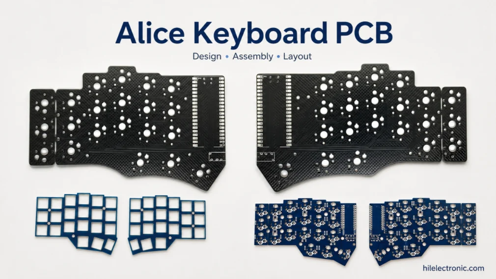
Alice Keyboard PCB Manufacturer | Custom Ergonomic Layout
An Alice keyboard PCB manufacturer must translate an...
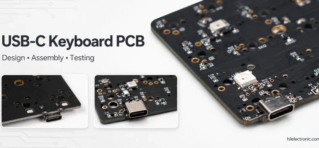
USB-C Keyboard PCB Manufacturer | ESD & Power Protection
A USB-C keyboard PCB manufacturer must control the...

Per-Key RGB Keyboard PCB Manufacturer & LED Assembly
A per-key RGB keyboard PCB manufacturer must control far...

Ortholinear Keyboard PCB Manufacturer | Custom Grid Layout
An ortholinear keyboard PCB manufacturer must preserve a...
How to get a quote for PCBs
Let‘s run DFM/DFA analysis for you and get back to you with a report. You can upload your files securely through our website. We require the following information in order to give you a quote:
-
- Gerber, ODB++, or .pcb, spec.
- BOM list if you require assembly
- Quantity
- Turn time
In addition to PCB manufacturing, we offer a comprehensive range of electronic services, including PCB design, PCBA, and turnkey solutions. Whether you need help with prototyping, design verification, component sourcing, or mass production, we provide end-to-end support to ensure your project’s success.
For PCBA services, please provide your BOM (Bill of Materials) and any specific assembly instructions. We also offer DFM/DFA analysis to optimize your designs for manufacturability and assembly, ensuring a smooth production process.