
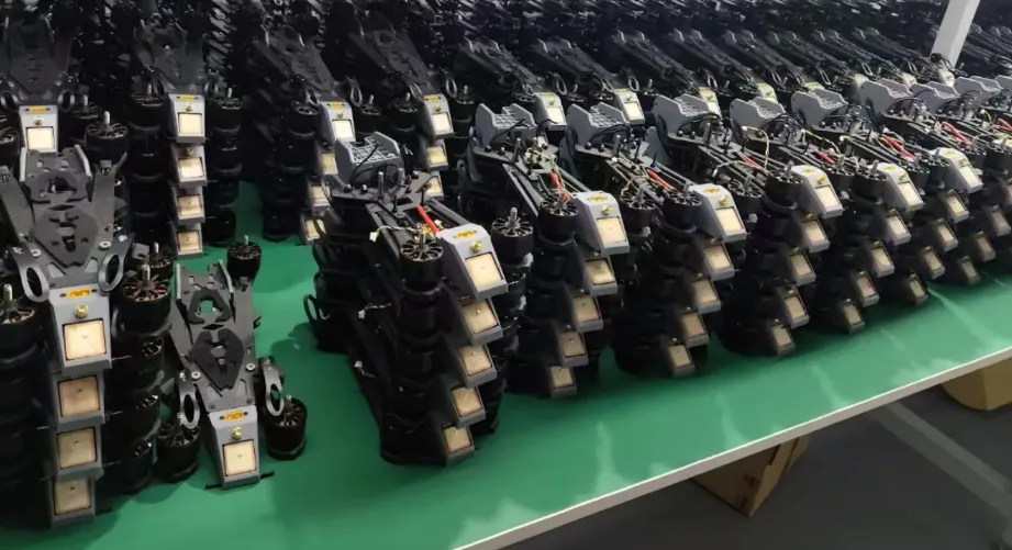
Drone Fiber Spool PCB Control System and Spool Electronics

Drone fiber spool PCB control system and deployment electronics refer to the control and interface hardware used in UAV fiber spool assemblies that manage fiber payout, retrieval, sensing, and subsystem coordination. In practical UAV platforms, the spool is not just a mechanical reel. It is an actively regulated deployment subsystem whose behavior depends on motor control, feedback processing, electrical protection, and stable PCB design.
A professional spool PCB typically combines motion control, sensor acquisition, interface communications, and deployment logic in one compact assembly. That makes it a mixed-domain board rather than a single-purpose motor controller. The same PCB may need to regulate spool speed, interpret tension or position data, estimate deployed fiber length, report subsystem health, and maintain reliable operation near sensitive fiber-routing structures.
Table of Contents
What the Drone Fiber Spool PCB Control System Does
A drone fiber spool PCB control system is the electronic layer that makes a fiber deployment mechanism predictable and usable in flight. It connects the spool assembly to the rest of the UAV platform and controls how the subsystem behaves during payout, retrieval, tension stabilization, and status reporting.
Main subsystem functions
- Drive the spool mechanism during fiber deployment and retrieval
- Acquire feedback from tension, position, or rotation sensors
- Estimate spool state, including deployed fiber length or remaining capacity
- Exchange status and control data with the UAV controller
- Support the interface conditions around the fiber-routing and handoff region
Why the control system matters
In real operation, spool instability can create multiple failure paths at once. Excessive tension can damage the fiber, slow response can allow slack to accumulate, and poor electrical partitioning can reduce sensing accuracy. For that reason, spool electronics should be treated as a mission-critical subsystem rather than as a secondary accessory board.
In broader UAV optical architectures, the spool assembly often supports the fiber-management side of the system described in the fiber optic drone PCB overview.
Motor Control and Deployment Electronics
The deployment electronics section controls the actuator that drives the spool. Depending on the platform, this may be a brushless motor, brushed DC motor, stepper motor, or another compact drive selected for torque, controllability, packaging, and duty-cycle requirements. The PCB therefore has to be built around the actual motion system instead of assuming one universal actuator type.
Typical motor-control blocks
- Power stage and driver circuitry
- Current sensing and fault protection
- Control MCU or motion-control processor
- Braking or deceleration handling
- Encoder or rotation interface
Deployment behavior the PCB must regulate
- Smooth spool acceleration during payout
- Controlled deceleration during retrieval
- Stable low-speed behavior when fiber motion is minimal
- Protection against abrupt torque changes and overshoot
In higher-performance systems, the control strategy may go beyond basic PWM speed regulation. Advanced designs may use more refined control schemes, including field-oriented control or other closed-loop motor-control approaches, when smooth low-speed torque and stable dynamic response are important to deployment quality.
Deployment electronics design priority
The power stage should be sized for peak load, transient current, and sustained thermal behavior rather than nominal running current alone. Thermal margin, copper weight, current-path width, and braking protection all need to reflect real deployment conditions, not just bench operation.
Sensing, Feedback, and Closed-Loop Regulation
Sensing is what allows the spool control system to respond to changing mechanical conditions instead of operating as an open-loop reel. In most serious UAV fiber deployment systems, the PCB reads one or more feedback sources and uses them to stabilize payout, retrieval, and fiber protection behavior.
Common sensor inputs
- Load cells or strain gauges for tension measurement
- Encoders for spool rotation or angular position
- Position sensors linked to dancer arms or guide structures
- Temperature sensors near power-stage components
- Status signals from subsystem interfaces or safety interlocks
What closed-loop regulation improves
- Prevents excessive tension spikes
- Reduces uncontrolled slack during deployment
- Improves repeatability across changing load conditions
- Helps maintain predictable spool-state estimation
On the PCB, the sensing chain often includes low-noise analog conditioning, filtered acquisition, and precise conversion before the control loop can use the data reliably. This is especially important when low-level sensor signals coexist on the same board as motor-drive transients and fast digital switching.
More advanced systems may combine direct feedback with predictive information from the aircraft controller or deployment state model. In practice, predictive inputs can improve response speed, while feedback corrects for disturbances, changing spool geometry, and model error.
| Feedback source | Primary function | Control value |
|---|---|---|
| Tension sensor | Detects load in the fiber path | Protects against over-tension and slack |
| Encoder | Tracks spool motion | Supports speed regulation and length estimation |
| Thermal sensing | Monitors power-stage heat rise | Supports derating and protection behavior |
Optical Interface Support and Fiber Routing Constraints
Although the spool PCB is primarily a control-system board, it also operates close to one of the most sensitive parts of the deployment mechanism: the fiber handoff and routing region. That means the board design must respect optical-path stability even when the PCB is not directly processing the optical signal itself.
Typical interface responsibilities near the fiber path
- Supporting connector or handoff-region mounting
- Preserving clearance around the fiber route
- Helping maintain serviceable cable or fiber geometry
- Supporting monitoring circuitry around the optical interface when required
Key routing and mechanical constraints
- Keep the handoff region free of unnecessary tall components
- Preserve minimum bend radius around the spool exit and guide structure
- Reduce contamination risk near connector or optical-interface surfaces
- Avoid mounting arrangements that amplify vibration near the handoff area
Depending on the architecture, the spool may connect into a fiber optic rotary joint, a managed routing loop, or another mechanical-optical transition between rotating and non-rotating sections. The support electronics at the opposite end of the fiber-management chain may also connect naturally to fiber optic canister board design where deployment and signal continuity must be coordinated across the wider system.
Why this section matters
A spool PCB can be electrically correct and still fail in service if the optical-interface region is mechanically unstable, contamination-prone, or poorly routed. Board design near the fiber handoff is therefore part of deployment reliability, not just packaging.
Mixed-Domain PCB Design Strategy
A professional drone fiber spool PCB is a mixed-domain board that combines power electronics, analog sensing, digital coordination, and interface-sensitive routing in one compact assembly. The layout strategy should therefore be based on partitioning, controlled return paths, and thermal discipline rather than on uniform placement.
Recommended functional zones
| Zone | Typical contents | Primary objective |
|---|---|---|
| Power zone | Driver stage, switching elements, current sensing, bulk capacitors | Confine current transients, EMI, and heat |
| Analog zone | Tension interface, amplifier chain, ADC, low-level filtering | Preserve sensor accuracy and reference stability |
| Digital/interface zone | MCU, communications, encoder logic, monitoring support | Coordinate control and subsystem communications |
Key layout priorities
- Keep noisy switching loops compact
- Use stable reference planes for analog and interface-sensitive paths
- Protect sensor inputs from high-current return paths
- Use controlled routing where interface speed requires it
- Plan heat spreading and copper distribution with real load conditions in mind
In more advanced designs, a 6-layer or 8-layer stack-up may be appropriate to improve EMI containment, reference continuity, thermal spreading, and routing discipline. Heavy copper may be needed in the motor-drive section, while internal ground structure can help stabilize analog and communication behavior. Where the spool subsystem also overlaps with wider optical communication functions, the same signal-integrity concerns discussed on the drone optical data link board page remain relevant.
Manufacturing, Assembly, and Functional Validation
Manufacturing a drone fiber spool PCB control system involves more than assembling a control board that powers up. The finished assembly has to remain stable under vibration, thermal cycling, load variation, and real deployment conditions. That requires the manufacturing process to support both electrical quality and mechanical repeatability.
Common assembly requirements
- Mixed through-hole and surface-mount processes
- Mechanically reinforced connector and mounting regions
- Selective masking around optical or interface-critical areas
- Controlled assembly handling near contamination-sensitive zones
Functional validation priorities
- Motor-drive verification under representative load
- Tension and position sensor calibration
- Communication-interface checks
- Thermal validation of the power stage
- Mechanical verification around the spool handoff region
Depending on design density and package type, inspection may also include AOI or X-ray for hidden joints and critical solder structures. Where the spool assembly participates directly in a larger optical control architecture, the board may overlap conceptually with a fiber-guided UAV control PCB depending on how communication and control functions are partitioned.
The manufacturing objective is not only to build a working PCB, but to produce a repeatable deployment-control subsystem that maintains stable behavior across production units. Highleap provides spool board fabrication and assembly services supporting the mixed-technology, reinforced mounting, and process control these boards require.

Recommended Posts

Per-Key RGB Keyboard PCB Manufacturer & LED Assembly
A per-key RGB keyboard PCB manufacturer must control far...

Ortholinear Keyboard PCB Manufacturer | Custom Grid Layout
An ortholinear keyboard PCB manufacturer must preserve a...
Keypad PCB Assembly Manufacturer | Custom Control Keypads
A keypad PCB assembly manufacturer may be building a...
Keyboard Matrix PCB Design & Manufacturing | Anti-Ghosting
Keyboard matrix PCB design converts a large number of...
How to get a quote for PCBs
Let us run DFM/DFA analysis for you and get back to you with a report.
You can upload your files securely through our website.
We require the following information in order to give you a quote:
-
- Gerber, ODB++, or .pcb, spec.
- BOM list if you require assembly
- Quantity
- Turn time
In addition to PCB manufacturing, we offer a comprehensive range of electronic services, including PCB design, PCBA (Printed Circuit Board Assembly), and turnkey solutions. Whether you need help with prototyping, design verification, component sourcing, or mass production, we provide end-to-end support to ensure your project’s success. For PCBA services, please provide your BOM (Bill of Materials) and any specific assembly instructions. We also offer DFM/DFA analysis to optimize your designs for manufacturability and assembly, ensuring a smooth production process.