
Copper Clad Laminate: Complete Material Selection Guide for PCB Engineers
 Sheets")
Every electrical property that matters in a printed circuit board — signal integrity, thermal stability, dielectric loss, impedance control — is determined before a single trace is routed. It is determined by the copper clad laminate chosen as the board’s substrate. A CCL is a composite material: copper foil bonded under heat and pressure to a reinforced insulating base, forming the raw material from which PCBs are fabricated. The properties of that insulating base — the dielectric constant, the dissipation factor, the glass transition temperature, the coefficient of thermal expansion — set a ceiling on what the finished board can achieve, regardless of how well everything else is executed.
This guide covers copper clad laminate selection from an engineering perspective: what the key parameters mean, which CCL types serve which application categories, where the boundaries between material grades lie, and how to specify CCL correctly to get the board performance your design requires.
Copper Clad Laminate — Key Parameters at a Glance
- Dk (Dielectric constant / Relative permittivity): Determines signal propagation speed and impedance. Lower Dk = faster propagation, better high-frequency performance. FR-4 Dk ≈ 4.2–4.5; Rogers PTFE ≈ 2.2–3.5.
- Df (Dissipation factor / Loss tangent): Determines how much signal energy is lost as heat in the dielectric. Critical for RF and high-speed designs. FR-4 Df ≈ 0.018–0.025; Rogers RO4350B Df ≈ 0.0037.
- Tg (Glass transition temperature): Temperature above which the laminate softens. Standard FR-4 Tg ≈ 130–140°C; high-Tg FR-4 Tg ≈ 150–170°C; polyimide Tg > 250°C.
- CTE (Coefficient of thermal expansion): How much the material expands per °C. Mismatch between CCL CTE and copper causes via barrel cracking over thermal cycles. Standard FR-4 Z-axis CTE ≈ 50–70 ppm/°C.
- Copper foil thickness: Standard 1 oz (35 µm). Heavy copper options: 2 oz, 3 oz, up to 6 oz for power electronics.
Get a CCL Specification Quote →
Table of Contents
- What Is Copper Clad Laminate and How Is It Made?
- The Four Parameters That Determine CCL Performance
- Five Major CCL Types: Properties, Costs, and Applications
- CCL Selection Guide: Matching Material to Application
- FR-4 vs. Rogers vs. High-Tg: When to Upgrade
- CCL Procurement in 2026: Availability, Pricing, and Lead Times
- Frequently Asked Questions
What Is Copper Clad Laminate and How Is It Made?
Copper clad laminate is a composite sheet material consisting of three functional components bonded together: a reinforcement layer (typically woven glass fabric or paper), a resin matrix (epoxy, polyimide, PTFE, or other polymers), and copper foil bonded to one or both faces. The combination determines the electrical, thermal, and mechanical properties of the resulting PCB substrate.
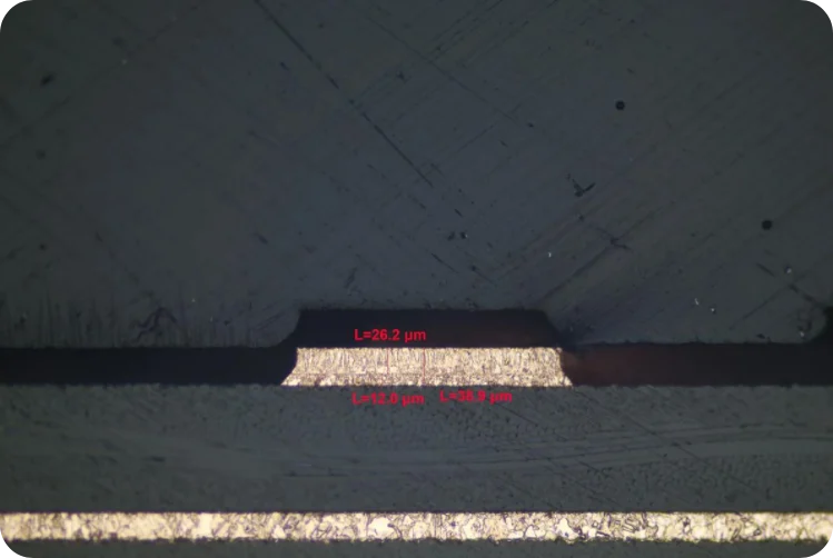
The manufacturing process begins with impregnation: reinforcement fabric is drawn through a resin bath, then passed through a drying oven to produce prepreg (pre-impregnated material) in a partially cured B-stage state. Multiple prepreg sheets are stacked with copper foil on the outer surfaces and compressed in a hydraulic press at temperatures typically between 170–200°C and pressures of 300–500 PSI. The heat causes the resin to flow and fully cure (C-stage), bonding all layers into a rigid laminated sheet. After pressing, the sheet is trimmed, inspected for thickness uniformity, tested for electrical properties, and cut to standard panel sizes — typically 1,020 × 1,220 mm or 1,020 × 915 mm.
The copper foil is produced separately by electrodeposition (ED foil) or rolling (RA foil). ED copper foil, produced by electroplating copper onto a rotating titanium drum, is the standard for rigid PCB applications. RA (rolled annealed) copper foil has a smoother surface and higher ductility, making it the correct choice for flexible PCBs where repeated bending is required.
The Four Parameters That Determine CCL Performance
Dielectric constant (Dk)
The dielectric constant describes how much a material slows the propagation of an electromagnetic wave compared to free space. In PCB terms, Dk directly determines signal propagation velocity and controlled-impedance trace geometry. The propagation velocity is proportional to 1/√Dk — a material with Dk = 4.0 propagates signals at half the speed of light, while a material with Dk = 2.2 propagates at 67% of the speed of light. This matters for timing-sensitive designs where signal delays must be matched across parallel traces.
Dk also affects the width of a controlled-impedance trace. For a 50Ω microstrip on standard FR-4 (Dk ≈ 4.2), the trace width for a 1.6mm board with 1 oz copper is approximately 2.8mm. On a Rogers RO4003C (Dk = 3.38), the same impedance requires a narrower trace — the lower Dk shifts the geometry. Engineers specifying controlled-impedance traces must know the actual Dk value of the laminate, not just its grade, because Dk varies with frequency and temperature.
Dissipation factor (Df)
The dissipation factor measures the fraction of signal energy lost as heat as it propagates through the dielectric. At low frequencies, Df contributes negligibly to signal loss. Above approximately 1 GHz, Df-related insertion loss becomes a significant design constraint. At 10 GHz, a standard FR-4 board with Df ≈ 0.020 will exhibit roughly 3–5 dB/10cm of dielectric loss — enough to corrupt a signal path over moderate trace lengths. Rogers RO4350B with Df = 0.0037 reduces this loss by approximately 5×, which is why high-frequency PCB designs require specialty laminate.
The practical consequence: if your design runs communications, clocks, or RF signals above approximately 1–2 GHz, Df becomes the primary material selection criterion.
Glass transition temperature (Tg)
Tg is the temperature at which the polymer resin transitions from a rigid glassy state to a soft rubbery state. Above Tg, the CCL loses dimensional stability, CTE increases dramatically, and sustained operation causes delamination and via barrel cracking over thermal cycles. The operating temperature of the board in service must remain comfortably below Tg — typically by a margin of at least 20–30°C.
Standard FR-4 with Tg 130–140°C is adequate for consumer electronics with ambient temperatures below 85°C. Industrial equipment in motor cabinets, outdoor enclosures, and automotive underhood applications requires high-Tg FR-4 (Tg 150–170°C) or polyimide (Tg > 250°C) to survive continuous elevated temperatures without substrate degradation.
Coefficient of thermal expansion (CTE)
CTE describes how much the material expands per unit temperature rise. The Z-axis CTE of FR-4 (through the board thickness) is typically 50–70 ppm/°C — significantly higher than the 17 ppm/°C CTE of copper. During thermal cycling, this mismatch creates mechanical stress in through-hole via barrels, eventually causing fatigue cracks in the copper plating. Boards with high layer counts (more copper, more thermal stress) and boards in applications with severe thermal cycling (automotive, outdoor industrial) require laminates with lower Z-axis CTE, or via designs that accommodate the mismatch. Low-CTE specialty laminates can reduce Z-axis CTE to 40 ppm/°C or lower.
Five Major CCL Types: Properties, Costs, and Applications
Standard FR-4
FR-4 (Flame Retardant Grade 4) is the universal baseline of PCB laminate — woven glass fabric reinforcement with brominated epoxy resin. It accounts for the majority of global CCL consumption because it balances electrical performance, mechanical strength, processability, and cost better than any alternative for general electronics. Its limitations are Dk and Df variability with frequency (Dk rises from ~4.2 at 1 MHz to ~4.5 at higher frequencies in some grades), and insufficient Tg for sustained high-temperature operation. For designs below 1 GHz and operating temperatures below 85°C, standard FR-4 is the correct and most cost-effective choice.
High-Tg FR-4
High-Tg FR-4 uses modified epoxy resin formulations — typically multifunctional epoxies or epoxy-cyanate ester blends — to elevate Tg to 150°C or 170°C. The electrical properties are nearly identical to standard FR-4; the improvement is purely in thermal stability. High-Tg FR-4 is the standard material for industrial PCB manufacturing applications including PLC boards, power electronics, and any board installed in enclosures with limited cooling where PCB surface temperature can exceed 80°C during operation.
Halogen-free laminates
Traditional FR-4 achieves its flame-retardant rating through bromine-containing compounds. Halogen-free grades replace these with phosphorus-based or nitrogen-based flame retardants to meet EU RoHS and REACH regulations and IEC 61249-2-21. The electrical properties are comparable or slightly better than standard FR-4 in some grades due to the different resin chemistry. The cost premium reflects the more complex resin formulation and narrower supplier base.
Rogers and PTFE-based high-frequency laminates
For applications where Df is the binding constraint — RF power amplifiers, phased array antennas, 5G mmWave infrastructure, radar front-ends — PTFE-based laminates are the standard engineering answer. Rogers RO4350B (Dk = 3.48, Df = 0.0037) and RO3003 (Dk = 3.00, Df = 0.0013) are the most widely specified. The manufacturing process for PTFE-based boards differs significantly from FR-4: PTFE requires special surface activation before plating, different drill parameters, and different press cycle profiles. Our high-frequency PCB fabrication process is specifically qualified for Rogers, Taconic, and PTFE-ceramic hybrid laminates.
Polyimide laminates
Polyimide offers the highest continuous operating temperature of all rigid PCB laminates, with no significant mechanical degradation below 250°C. It is the standard for aerospace flight electronics, military equipment, and downhole oil and gas instrumentation. Polyimide is also the substrate for flexible circuits (FPC) where its combination of high-temperature stability and mechanical flexibility cannot be achieved with FR-4. The cost premium and more difficult processing limit polyimide to applications where its thermal properties are genuinely required.
CCL Selection Guide: Matching Material to Application
Consumer electronics / general digital boards
Industrial automation / PLC / power electronics
High-speed digital (1–5 GHz) — DDR5, PCIe Gen 4/5, 25G Ethernet
RF / microwave / 5G (above 5 GHz)
Aerospace / military / downhole / high-temperature industrial
FR-4 vs. Rogers vs. High-Tg: When to Upgrade
The decision to upgrade from standard FR-4 is driven by a specific measurable design constraint — not by a general desire for “better” materials. Upgrading material without a specific performance need adds cost without benefit.
Upgrade from standard FR-4 to high-Tg FR-4 when: the board will operate in an environment where the PCB surface temperature under load exceeds 80°C; the design uses more than 8 layers where the thermal stress accumulation across layer count warrants higher Tg; or the application has a service life exceeding 10 years in a thermally demanding environment.
Upgrade from FR-4 to mid-loss or low-loss FR-4 derivatives (not PTFE) when: signal frequencies on critical paths run between 1–5 GHz and insertion loss budget calculations show FR-4 Df will cause margin failures; this applies to AI server backplanes running PCIe Gen 5, high-speed networking equipment running 25G or 100G Ethernet, and similar high-density interconnect designs where PTFE is not warranted but standard FR-4 is insufficient.
Upgrade from FR-4 to PTFE-based Rogers or Taconic laminates when: any signal path runs above approximately 5 GHz, or Df below 0.005 is explicitly required by link budget analysis. Do not upgrade to Rogers simply because the design “might benefit” — the processing complexity and cost impact of PTFE laminates require engineering justification.
Understand that mixed-material constructions are common for high-frequency designs: Rogers material on specific high-frequency signal layers with FR-4 on the remaining layers. This hybrid approach reduces cost while placing the high-performance material only where signal loss would actually occur. Highleap Electronics’ controlled-impedance PCB fabrication accommodates hybrid stack-up designs with mixed laminate types.
CCL Procurement in 2026: Availability, Pricing, and Lead Times
The copper clad laminate procurement environment in 2026 is significantly tighter than historical norms. Copper prices hit a record $13,300/tonne in January 2026, and CCL prices have risen 45% versus prior periods in some grades. More critically, certain high-end CCL grades — particularly M7 through M10 ultra-low-loss laminates for AI server PCBs — have moved from price pressure to genuine availability constraint, with lead times extending to 6 months and a quota system imposed by some suppliers.
For standard FR-4 and high-Tg FR-4, the situation is less severe but still meaningfully tighter than 2024. Lead times for standard-grade laminates have extended from 2–4 weeks to 4–8 weeks. For designs that require specialty laminates (Rogers, PTFE, polyimide), early engagement with the PCB manufacturer on material availability is essential before finalizing production schedules.
When sourcing PCBs in the current environment: specify material by grade and performance parameters rather than by brand, which allows the manufacturer to qualify equivalent materials when the primary brand faces availability constraints; plan production schedules with 6–10 week material lead time built in for standard FR-4 and 12–16 weeks for specialty laminates; and for critical production runs, discuss forward material purchasing with your PCB manufacturer to lock in availability ahead of the production schedule.
Highleap Electronics — CCL Specification and Material Support
We manufacture PCBs across the full CCL spectrum — standard FR-4, high-Tg FR-4 (150°C and 170°C), halogen-free grades, Rogers and Taconic PTFE-based laminates, and polyimide. Our engineering team reviews material specification during DFM and advises on equivalent grades when primary materials face availability constraints. For high-frequency and high-speed designs, we provide impedance stack-up modeling before production commitment.
Frequently Asked Questions
What is copper clad laminate used for?
Copper clad laminate is the base material from which all rigid printed circuit boards are fabricated. The CCL is processed through imaging, etching, drilling, plating, and surface finishing to create the finished PCB. Every electrical property of the PCB — signal integrity, thermal stability, impedance control — is fundamentally determined by the CCL material selected. Different application environments require different CCL types: standard FR-4 for consumer electronics, high-Tg FR-4 for industrial and automotive, and PTFE-based laminates for RF and microwave applications.
What is the difference between FR-4 and Rogers laminate?
FR-4 is a glass-epoxy laminate with Dk ≈ 4.2–4.5 and Df ≈ 0.018–0.025. Rogers laminates (such as RO4350B) use PTFE or ceramic-filled hydrocarbon systems to achieve Dk in the range 2.2–3.5 and Df as low as 0.001–0.005. The lower Dk gives Rogers laminates better signal propagation speed and lower insertion loss at high frequencies. Rogers is necessary for designs above approximately 5 GHz where FR-4 Df causes unacceptable signal loss. The cost differential is 5–20× depending on the specific Rogers product.
What Tg should I specify for an industrial PCB?
For industrial PCBs installed in electrical cabinets, near motor drives, or in any environment where PCB surface temperature can reach 70–100°C during operation, specify high-Tg FR-4 with Tg of 150°C minimum, preferably 170°C. Standard FR-4 (Tg 130–140°C) has inadequate thermal margin for these environments. The cost premium over standard FR-4 is typically 20–50%, which is justified by the reliability improvement in thermally demanding installations.
What is the dielectric constant of FR-4?
Standard FR-4 has a dielectric constant of approximately 4.2–4.5 at 1 GHz. The value varies with frequency (it is higher at low frequencies and decreases slightly at high frequencies), temperature, and specific manufacturer formulation. For controlled-impedance calculations, use the specific Dk value from the laminate manufacturer’s datasheet at the operating frequency, not a generic FR-4 Dk value. The typical range for controlled-impedance calculations is 4.2–4.4 at frequencies relevant to high-speed digital designs.
Can FR-4 be used for RF PCBs?
FR-4 can be used for RF designs below approximately 1–2 GHz with some limitations. Above 2 GHz, the Df of standard FR-4 (0.018–0.025) causes insertion loss that exceeds the link budget for most RF systems. The dielectric constant of FR-4 also varies more with temperature and frequency than specialty RF laminates, making precise impedance control difficult at high frequencies. For RF designs above 2 GHz, mid-loss FR-4 derivatives or PTFE-based laminates are required. For designs above 5 GHz, PTFE-based laminates are the standard specification.

Recommended Posts

Custom Rogers RO4835 PCB Fabrication & Assembly Services
Figure 1. Rogers RO4835 PCBRogers RO4835 PCB is a...

Nelco N4000-13 PCB Material and Manufacturing Guide | Highleap Electronics
Figure 1. Nelco N4000-13 PCBNelco N4000-13 PCB is a...

Rogers RT/duroid 6002 PCB Manufacturer — Specifications, Stackup, Quote
Figure 1. Rogers RT/duroid 6002Rogers RT/duroid 6002 is...

Miniaturize Antennas with Rogers TMM Laminates
Figure 1. Rogers TMM Executive Summary: Rogers TMM...
How to get a quote for PCBs
Let us run DFM/DFA analysis for you and get back to you with a report.
You can upload your files securely through our website.
We require the following information in order to give you a quote:
-
- Gerber, ODB++, or .pcb, spec.
- BOM list if you require assembly
- Quantity
- Turn time