
Glass PCB vs FR4 Choosing the Right PCB Material

Glass PCB vs FR-4 is not a general “newer is better” comparison. FR-4 remains the correct material for most conventional circuit boards because it is low cost, widely available, mechanically forgiving, and easy to fabricate. Glass PCB becomes the better choice only when the design depends on properties FR-4 cannot provide, such as low RF loss at higher frequencies, optical transparency, CTE compatibility with silicon, or long-term stability in moisture-sensitive and high-temperature environments. The right decision is therefore application-driven, not trend-driven. For the broader technology background, see glass PCB overview.
Quick answer
Choose FR-4 for mainstream digital, power, and control boards where cost, supply flexibility, and mechanical toughness matter most. Choose glass PCB when the design requires low dielectric loss, optical transparency, tight CTE match to silicon, or environmental stability that standard FR-4 cannot provide.
Table of Contents
What Is the Difference Between Glass PCB and FR-4?
The main difference between glass PCB and FR-4 is the substrate system itself. FR-4 is an epoxy-glass laminate built around woven fiberglass and resin. Glass PCB uses a glass substrate such as borosilicate, fused silica, soda-lime, or aluminosilicate, depending on the application. That material difference changes nearly every important performance category, including dielectric loss, thermal expansion, moisture behavior, transparency, fine-feature capability, and long-term dimensional stability.
FR-4 is the standard choice because it is practical, inexpensive, and suitable for the majority of low- to mid-frequency circuit boards. Glass PCB is not a universal replacement. It is a specialized platform used when the board must do something FR-4 fundamentally cannot do well enough. Typical examples include mmWave RF routing, transparent circuits, high-density package substrates, and boards that must remain stable under thermal or chemical stress over long service life.
The decision should therefore begin with application requirements, not with material prestige. If the design does not need the defining advantages of glass, FR-4 usually remains the better engineering and commercial choice.
Glass PCB vs FR-4 Material Properties
The most useful way to compare glass PCB and FR-4 is to examine where each material clearly wins. The table below focuses on the practical properties that most often drive the material decision.
| Property | FR-4 | Glass PCB | Practical impact |
|---|---|---|---|
| Dielectric loss | Higher, especially as frequency rises | Lower and more stable | Glass is preferred for mmWave, radar, and low-loss RF paths |
| CTE relative to silicon | Poorer match | Much closer match | Glass is better for advanced package and die-attach structures |
| Moisture absorption | Present | Near zero | Glass offers better long-term dimensional and electrical stability |
| Optical transparency | Opaque | Transparent or semi-transparent depending on design | Only glass works for transparent PCB applications |
| Mechanical toughness | More impact tolerant | More brittle | FR-4 is better for drop-prone and handling-intensive products |
| Cost and supply chain | Lower cost, broad supplier base | Higher cost, narrower supplier base | FR-4 is usually better unless glass-specific performance is required |
| Fine-feature potential | Good for mainstream PCB design | Can support much finer structures in the right process flow | Glass is stronger for advanced interconnect and packaging structures |
For RF and microwave work, the biggest difference is dielectric loss. For packaging, the biggest difference is CTE match to silicon. For transparent and optical products, FR-4 is eliminated immediately because it is opaque. For mainstream industrial, power, and digital boards, FR-4 remains difficult to displace because its cost-performance ratio is still better in most routine designs.
Not all glass substrates behave the same way. Borosilicate, fused silica, and aluminosilicate each have different tradeoffs in loss, transparency, mechanical strength, and cost. If the project is already narrowed to one specific glass family, the material details are better addressed in the borosilicate glass PCB guide and related substrate-specific pages.
When Glass PCB Is Better Than FR-4
Glass PCB is the better choice when the substrate itself must contribute performance that FR-4 cannot realistically deliver. This usually happens in one of four situations: high-frequency signal loss becomes unacceptable, silicon compatibility matters at the package level, transparency is mandatory, or long-term environmental stability is central to the design.
Glass core and package-style substrates
When the design needs a substrate closer to semiconductor packaging than standard PCB routing, glass becomes attractive because its CTE is much closer to silicon than FR-4. This reduces thermomechanical stress at fine bump pitch and improves stability in advanced package-style structures. That is the design logic behind glass core PCB applications.
Transparent and optically active circuits
When the circuit must allow light to pass through the board, FR-4 is no longer a real option. Transparent display structures, optically aligned sensors, and transparent lighting products depend on glass as the substrate platform. This is the same design space discussed in transparent PCB applications.
Long-life and harsh-environment reliability
Where moisture absorption, chemical exposure, or high-temperature stability create long-term risk for organic laminates, glass offers a cleaner and more stable material system. These advantages matter in industrial, automotive, aerospace, and precision sensing systems that remain in service for years rather than months.

When FR-4 Is Better Than Glass PCB
FR-4 remains the better choice whenever glass-specific performance is not required. This includes the majority of digital control boards, low-frequency mixed-signal electronics, mainstream power conversion boards, and products where cost, supply flexibility, and mechanical durability are more important than optical or high-frequency performance.
General-purpose digital and power boards
If the design operates at modest frequencies, does not require transparency, and does not involve advanced package-style interconnect, FR-4 usually remains the most rational material choice. The ecosystem is mature, prototyping is easier, and the manufacturing cost is significantly lower.
Products exposed to handling shock or drop conditions
Glass is mechanically more fragile than FR-4. If the board will be handled roughly, installed in cost-sensitive consumer products, or expected to survive impact scenarios without special protection, FR-4 often has the advantage.
Programs needing broad supplier flexibility
FR-4 is available from a very large manufacturing base with familiar design rules and faster mainstream turnaround. If the design can meet performance goals on FR-4, the wider supplier base alone may justify staying with it.
Projects where board cost dominates system cost
Glass can make sense when its performance advantage removes other expensive design burdens, but if the board itself is the dominant cost driver and no unique glass benefit is required, FR-4 generally wins on commercial grounds.
How to Choose Glass PCB vs FR-4 for Your Project
This is the most important part of the decision. A good comparison should not stop at property tables. It should help determine which material is correct for a real design. The best way to do that is to move through the decision in a fixed order, starting from function, then electrical performance, then mechanical and environmental requirements, and finally manufacturability and total system cost.
Step 1: Decide whether the substrate must do more than support copper routing
If the board only needs to hold conductors, components, and ordinary interconnect, FR-4 is usually the starting point. If the substrate must also transmit light, remain dimensionally stable at very high frequency, match silicon more closely, or resist moisture-driven drift over long service life, glass moves into consideration immediately. This first step eliminates many unnecessary material debates.
Step 2: Check whether RF loss makes FR-4 impractical
If the project includes mmWave RF paths, compact radar routing, antenna feed networks, or other circuits where dielectric loss directly determines system feasibility, glass may be required rather than optional. If the electrical design remains comfortably within the loss budget of FR-4, then glass has to justify itself through some other requirement.
Step 3: Check whether the board must interact closely with silicon or package-style structures
When bump pitch, die attach stability, or package flatness become design priorities, glass gains value because its thermal expansion behavior is much closer to silicon. This is not relevant for ordinary PCB layouts, but it matters greatly in advanced substrates and interconnect structures.
Step 4: Check for transparency or optical alignment requirements
If the board must be transparent, semi-transparent, or optically aligned with a sensor, emitter, or display zone, the decision is usually made here. FR-4 is opaque, so there is no meaningful workaround at the substrate level.
Step 5: Evaluate environmental life, not just immediate performance
If the board must remain stable under humidity, chemical exposure, thermal cycling, or long service intervals, glass may justify its cost through lower risk over time. If the product is short-life, cost-sensitive, and electrically undemanding, FR-4 often remains the better answer.
Step 6: Compare total system cost, not just board price
This is where many decisions go wrong. A glass board can cost more than FR-4, but that alone does not make it the wrong choice. If glass reduces RF loss enough to simplify the front-end, eliminates substrate-driven reliability issues, or enables a transparent or package-style architecture that FR-4 cannot support, the higher board cost may still reduce the total cost or total risk of the system. Conversely, if the design works well on FR-4, changing to glass may only increase cost without improving the product in a meaningful way.
Practical decision summary
- Choose glass PCB for mmWave RF, transparent circuits, glass core packaging, and long-life harsh-environment structures.
- Choose FR-4 for mainstream digital, power, control, and cost-sensitive boards without special glass-driven requirements.
- Use both in one system when only part of the product needs glass-level performance and the rest can remain on FR-4.
In many advanced systems, the best architecture is not glass or FR-4 everywhere. It is a mixed approach. Glass may be used only in the RF section, transparent section, or package section, while FR-4 continues to handle digital control, power management, and support electronics. That kind of partitioning often produces the best balance of performance, manufacturability, and cost.
Glass PCB vs FR-4 FAQ
Is glass PCB always better than FR-4?
No. FR-4 is still the correct choice for most conventional circuit boards. Glass becomes better only when the design needs lower RF loss, transparency, silicon-compatible expansion behavior, or more stable long-term environmental performance.
Can glass PCB and FR-4 be used in the same product?
Yes. This is often the best system-level solution. Use glass only where its advantages are necessary, and keep FR-4 where it remains more economical and mechanically practical.
Does glass PCB always cost much more?
The board cost is usually higher, but the correct comparison is total system cost. In some RF, transparent, or package-style applications, glass may reduce system complexity enough to justify the substrate premium.
When should I look at manufacturing questions instead of material questions?
Once the application clearly points toward glass, the next step is manufacturability review. That is where the discussion moves from material comparison into routing, structure type, interconnect approach, and process planning, as covered in glass PCB manufacturing.
Which glass type is better for RF, borosilicate or fused silica?
Borosilicate is often sufficient for many high-frequency designs, while fused silica becomes more attractive as loss sensitivity becomes more extreme. If the project has already narrowed to one glass family, start with the borosilicate glass PCB page and compare it against the actual frequency range and loss budget of the design.
How should I start a real project review?
If you already have a layout, stack idea, or use case in mind, send the files and requirements through the Highleap quoting team so the material decision can be checked against the actual structure rather than against generic assumptions.

Recommended Posts
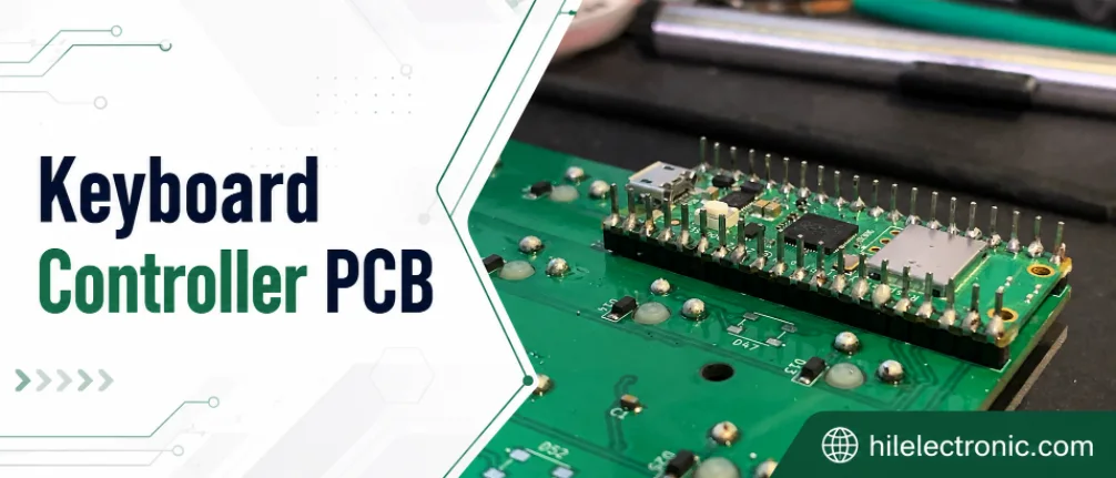
Keyboard Controller PCB Manufacturer | MCU Programming
A keyboard controller PCB manufacturer must deliver a...
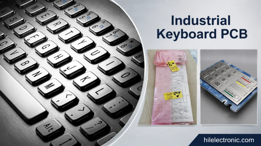
Industrial Keyboard PCB Manufacturer | Durable Control Panels
An industrial keyboard PCB manufacturer must design the...
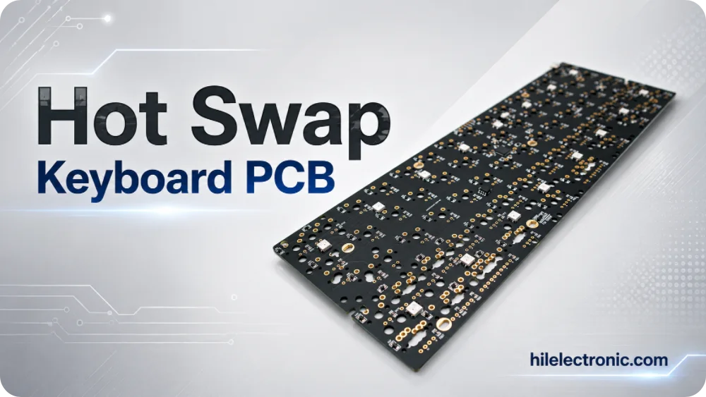
Hot Swap Keyboard PCB Manufacturer | Socket Assembly & Testing
A hot swap keyboard PCB manufacturer must control the...
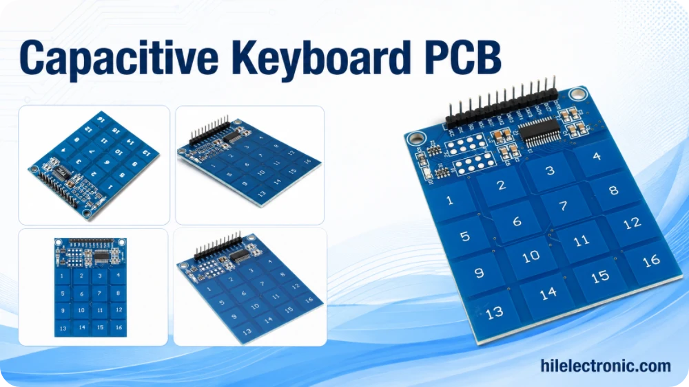
Capacitive Keyboard PCB Manufacturer | Touch Sensor PCBA
A capacitive keyboard PCB manufacturer must control the...
How to get a quote for PCBs
Let us run DFM/DFA analysis for you and get back to you with a report.
You can upload your files securely through our website.
We require the following information in order to give you a quote:
-
- Gerber, ODB++, or .pcb, spec.
- BOM list if you require assembly
- Quantity
- Turn time
In addition to PCB manufacturing, we offer a comprehensive range of electronic services, including PCB design, PCBA (Printed Circuit Board Assembly), and turnkey solutions. Whether you need help with prototyping, design verification, component sourcing, or mass production, we provide end-to-end support to ensure your project’s success. For PCBA services, please provide your BOM (Bill of Materials) and any specific assembly instructions. We also offer DFM/DFA analysis to optimize your designs for manufacturability and assembly, ensuring a smooth production process.