
PCB Overcurrent Protection: Practical Design Guide Using PCB Fuses

1. Introduction: Why PCB Overcurrent Protection Matters
Overcurrent and short-circuit events rank among the most destructive failure modes in electronic systems. Uncontrolled current surges can burn traces, destroy ICs, overheat power devices, and create fire hazards—especially in battery-powered applications.
Effective PCB overcurrent protection forms the foundation of reliable design. Among all protection strategies, PCB-mounted fuses remain the most direct and dependable solution. However, protection effectiveness depends not only on component selection but also on manufacturing quality—soldering profiles, thermal management, and placement decisions all play critical roles.
2. What Is PCB Overcurrent Protection?
2.1 Core Objective
PCB overcurrent protection ensures rapid circuit disconnection when current exceeds safe operating limits. This prevents thermal runaway and protects downstream components from permanent damage.
2.2 Protection Mechanisms
Three primary mechanisms provide overcurrent protection on PCBs:
- Fusing – Permanent interruption through metal element melting, providing definitive fault isolation.
- Current limiting – Active circuits that restrict current flow without breaking the circuit.
- Resettable protection – PTC devices that increase resistance during faults and recover automatically.
This article focuses on two key device categories: traditional PCB fuses for permanent fault interruption, and PTC resettable fuses for recoverable protection.

Figure 1. PCB Fuses
3. Types of PCB Fuses
3.1 Classification by Response Speed
Fast-acting fuses open within milliseconds of reaching their rated current. I recommend these for protecting sensitive ICs, lithium battery circuits, and precision analog modules where even brief overcurrent events cause damage.
Slow-blow (time-delay) fuses tolerate transient inrush currents before opening. These suit applications with high startup surges—motors, transformers, and switch-mode power supplies (SMPS) that draw 5–10× rated current during turn-on.
3.2 Classification by Construction
Metallic fuses use a calibrated wire or foil element that melts permanently at rated current. They offer predictable performance and low cost but require replacement after each event.
Polymer PTC resettable fuses contain conductive polymer that transitions to high-resistance state when heated by overcurrent. After fault removal and cooling, they automatically restore conductivity—ideal for field-deployed equipment where manual replacement is impractical.
3.3 Classification by Mounting Type
Mounting method directly affects assembly process and application suitability:
- SMD fuses – Surface-mount packages (0603, 1206, 2410) compatible with automated pick-and-place, optimized for high-volume production.
- Through-hole fuses – Leaded packages providing robust mechanical connection for high-current or high-vibration environments.
- Fuse holders – Chassis or PCB-mounted sockets enabling field replacement without soldering, common in industrial and serviceable equipment.
Choosing the right mounting style ensures the fuse can withstand real-world operating conditions while aligning with your assembly and maintenance requirements.
4. How PCB Fuses Work
4.1 Metallic Fuse Operation
Under normal conditions, current flows through a precisely calibrated metal element with minimal resistance. When fault current generates heat exceeding the element’s melting point, the conductor vaporizes and creates an open circuit. The I²t rating (current-squared × time) defines the energy required for interruption—lower values indicate faster response.
4.2 PTC Resettable Fuse Behavior
PTC devices exploit the sharp resistance increase of conductive polymers near their crystalline transition temperature. Overcurrent-induced heating triggers this transition within milliseconds, limiting current to safe microamp levels. Once power is removed and the device cools, resistance drops and normal operation resumes. Key parameters include hold current (maximum continuous safe current), trip current (minimum current causing transition), and time-to-trip characteristics.
5. How to Select PCB Overcurrent Protection Devices
5.1 Determine Operating Current with Safety Margin
Select a fuse rated at 125% of maximum steady-state current. For circuits with inrush current, verify that the I²t let-through during turn-on remains below the fuse’s pre-arcing I²t value to prevent nuisance tripping.
5.2 Verify Voltage Rating
The fuse voltage rating must exceed maximum system voltage. Note that AC and DC ratings often differ—DC arcs are harder to extinguish, so DC ratings are typically lower. Using an under-rated fuse risks sustained arcing after interruption.
5.3 Confirm Breaking Capacity
Breaking capacity defines the maximum fault current a fuse can safely interrupt. Insufficient breaking capacity may cause the fuse to rupture violently or fail to clear the fault. Power supply and industrial applications require careful attention to this specification.
5.4 Match Response Speed to Load Type
Select response speed based on load characteristics:
- Fast-acting – Semiconductor protection, battery circuits, precision instrumentation.
- Slow-blow – Motor drives, SMPS, inductive loads with startup transients.
5.5 Account for Environmental Factors
Environmental conditions directly affect fuse performance:
- Temperature – Elevated ambient reduces current-carrying capacity; apply manufacturer derating curves.
- Humidity – Moisture accelerates terminal oxidation; consider conformal coating or sealed packages.
- Vibration – Automotive and industrial applications require mechanically robust mounting to prevent fatigue failures.
Accounting for these environmental factors from the start ensures stable fuse behavior throughout the product’s entire operating lifetime.
For production planning, it also helps to compare this topic with PCBA functional testing and ENIG PCB finish before finalizing the fabrication or assembly package.

Figure 2. Fuse Temperature Derating Curve
6. PCB Overcurrent Protection Design Guidelines
6.1 Optimal Fuse Placement
Position fuses near the power input, before the main power distribution network. Avoid placing fuses adjacent to high-temperature components such as power inductors or MOSFETs. Reserve adequate clearance for test probe access and potential field replacement.
6.2 SMD Fuse Soldering Considerations
Reflow soldering profiles significantly impact SMD fuse reliability. The metal fuse element is sensitive to peak temperatures—exceeding manufacturer limits (typically 260°C for 10 seconds maximum) may alter calibration or cause premature degradation. Always verify compatibility between your reflow profile and fuse specifications.
6.3 PCB Trace Current Capacity
Ensure trace width supports at least 150% of fuse rated current. If the trace fuses before the protection device, the designed protection scheme fails. Consider increased copper weight (2 oz or heavier) for power paths carrying significant current.
7. Testing and Verification for PCB Fuse Assemblies
Comprehensive testing validates both component selection and manufacturing quality. Essential verification includes:
- Current/trip testing – Confirms fuse opens at rated current within specified time.
- Thermal imaging – Identifies hot spots indicating inadequate trace capacity or poor solder joints.
- AOI inspection – Verifies solder joint integrity and correct component placement.
- Environmental testing – Temperature cycling and thermal shock per IPC standards confirm long-term reliability.
These tests ensure PCB overcurrent protection performs as designed throughout product lifetime.
8. Applications of PCB Overcurrent Protection
8.1 Consumer Electronics
Smartphones, laptops, and tablets rely on compact SMD fuses to protect lithium batteries and charging circuits. Space constraints demand miniature packages with precise current ratings.
8.2 Medical Devices
Medical equipment requires fuses meeting IEC 60601 safety standards. High reliability and predictable failure modes protect both patients and equipment.
8.3 Automotive Electronics
Automotive PCB fuse applications demand AEC-Q200 qualified components capable of withstanding extreme temperatures (−40°C to +125°C) and sustained vibration.
8.4 Industrial Control Systems
Industrial applications often specify slow-blow fuses with high breaking capacity to handle motor inrush currents and potential high-energy faults.
9. Common PCB Overcurrent Protection Design Mistakes
Even experienced engineers make these errors:
- Ignoring breaking capacity – Selecting fuses based solely on current rating without verifying interrupting capability.
- Wrong response speed – Using fast-acting fuses in circuits with significant inrush current causes nuisance tripping.
- Poor thermal placement – Mounting fuses near heat-generating components reduces effective current rating.
- Neglecting derating – Failing to account for elevated ambient temperature leads to premature failure.
- Undersized traces – PCB conductors that fuse before the protection device defeat the protection scheme entirely.
Avoiding these pitfalls not only strengthens your PCB overcurrent protection strategy but also ensures the fuse performs exactly as intended when a real fault occurs.
10. Conclusion
PCB overcurrent protection directly impacts product safety, regulatory compliance, and field reliability. I believe engineers should address fuse selection and placement early in the design phase—retrofitting protection after layout completion often compromises effectiveness.
Proper implementation requires matching device characteristics to application requirements: response speed to load type, voltage rating to system maximum, and breaking capacity to potential fault current. Equally important, manufacturing processes must respect component limitations to preserve designed performance.

Recommended Posts

RF Transceiver PCB Manufacturing and Assembly
Table of contentsRF Transceiver PCB Manufacturing and...
RFSoC Board PCB Manufacturing and Assembly One-Stop Service
Highleap Electronics supports customer-designed RFSOC...
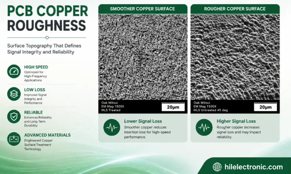
PCB Copper Roughness: Signal Loss, Material Selection and Manufacturing Control
Table of contentsWhat Is PCB Copper Roughness?How Copper...
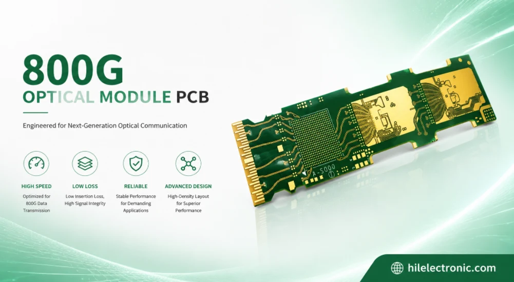
800G Optical Module PCB Manufacturing and Assembly Service
Table of contentsWhat Makes an 800G Optical Module PCB...
How to get a quote for PCBs
Let‘s run DFM/DFA analysis for you and get back to you with a report. You can upload your files securely through our website. We require the following information in order to give you a quote:
-
- Gerber, ODB++, or .pcb, spec.
- BOM list if you require assembly
- Quantity
- Turn time
In addition to PCB manufacturing, we offer a comprehensive range of electronic services, including PCB design, PCBA, and turnkey solutions. Whether you need help with prototyping, design verification, component sourcing, or mass production, we provide end-to-end support to ensure your project’s success.
For PCBA services, please provide your BOM (Bill of Materials) and any specific assembly instructions. We also offer DFM/DFA analysis to optimize your designs for manufacturability and assembly, ensuring a smooth production process.