
Rogers TMM PCB Manufacturer and Assembly Supplier: Highleap Electronics
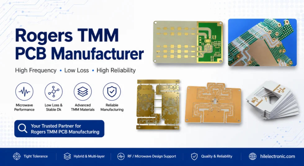
Table of Contents
- Highleap Electronics Rogers TMM PCB Manufacturing and Assembly
- Rogers TMM Material Use and Grade Control
- RF Stackup Review and DFM Before Production
- Rogers TMM PCB Fabrication Process Control
- Rogers TMM PCB Assembly and Project Support
- Prototype, Trial Order and Production Transfer
- Quality Control, Documentation and Change Management
- Quote Package, Supplier Evaluation and FAQ
Highleap Electronics is a PCB manufacturing and PCB assembly electronic factory. We manufacture finished printed circuit boards and assembled PCB products based on customer design files, material callouts, stackups, drawings and assembly requirements. We do not manufacture Rogers TMM raw laminate material. Rogers TMM is a high-frequency laminate family supplied by Rogers Corporation, and Highleap Electronics uses customer-specified Rogers TMM laminates to fabricate and assemble Rogers TMM PCBs for RF, microwave, antenna, radar, satellite communication, test fixture, power amplifier and high-reliability electronic projects.
A Rogers TMM PCB manufacturer in this context means a PCB fabricator and PCBA supplier that can process the specified Rogers TMM laminate into finished bare boards or assembled boards. The manufacturing responsibility includes material confirmation, stackup review, RF DFM, CAM engineering, controlled impedance planning, drilling, routing, copper plating, surface finish, inspection, documentation, packaging and assembly coordination when PCBA service is required. The laminate material itself remains Rogers material; the PCB and PCBA manufacturing service is provided by Highleap Electronics.
Highleap Electronics also manufactures other PCB technologies for electronic products, including FR4 PCBs, high Tg PCBs, multilayer PCBs, HDI PCBs, impedance-controlled PCBs, flexible PCBs, rigid-flex PCBs, aluminum PCBs, copper substrate PCBs and other high-frequency material PCBs. Rogers TMM PCB service is part of this broader PCB and PCBA manufacturing capability. For material background, see the Rogers TMM high-frequency PCB material guide. For detailed process guidance, see the Rogers TMM PCB fabrication process guide. For cost planning, see the Rogers TMM PCB price guide.
Manufacturing position: Highleap Electronics is a PCB and PCBA manufacturer. We fabricate and assemble boards using specified Rogers TMM material. We do not produce the raw Rogers TMM laminate.
Service scope: Rogers TMM PCB fabrication, Rogers TMM PCB prototype, Rogers TMM PCB assembly support, RF stackup review, controlled impedance support, small-batch production and volume manufacturing for electronic products.
Highleap Electronics Rogers TMM PCB Manufacturing and Assembly
PCB and PCBA manufacturing role
Highleap Electronics builds Rogers TMM PCBs from released manufacturing files. The normal input package includes Gerber, ODB++ or IPC-2581 data, drill files, fabrication drawing, stackup, material grade, copper weight, surface finish, impedance targets, quantity, lead time and inspection requirements. When assembly is included, the package also includes BOM, pick-and-place file, assembly drawing, polarity notes, component specifications, reflow requirements and packaging instructions.
The manufacturing role is practical and controlled. Highleap does not change the laminate grade, dielectric thickness, surface finish or stackup without customer approval. If a project specifies Rogers TMM6, the build is reviewed as a TMM6 board. If TMM10i is required for a compact resonator or microwave circuit, the material callout is treated as a functional requirement rather than a replaceable purchasing item. This helps keep RF performance, repeatability and qualification history aligned.
Rogers TMM PCB service scope
Rogers TMM PCB service can include bare board fabrication only or complete PCBA support depending on the project. Bare board service covers material confirmation, CAM, panelization, imaging, etching, drilling, plating, solder mask if required, surface finish, routing, electrical test, impedance measurement and final inspection. PCBA service can include component sourcing support, SMT assembly, through-hole assembly, connector installation, shield placement, selective inspection, cleaning control and packaging.
The most suitable service route depends on project stage. A laboratory prototype may require fast fabrication and a few assembled test boards. An engineering validation lot may require impedance coupons, microsection and connector launch assembly. A production program may require locked stackup, material traceability, first article approval, repeatable packaging and controlled engineering change handling. A supplier with both PCB and PCBA capability can coordinate these steps more efficiently than a supplier focused only on bare boards.
Supported Rogers TMM PCB project types
Highleap Electronics can support Rogers TMM PCB projects where the PCB is part of the RF signal path or a high-reliability electronic assembly. Typical board types include two-layer microstrip boards, stripline boards, grounded coplanar waveguide boards, antenna PCBs, microwave filter boards, coupler boards, RF power amplifier boards, low-noise amplifier boards, radar module boards, satellite communication boards, test fixtures and hybrid boards combining Rogers TMM with other PCB materials.
Application requirements should be written into the fabrication notes when possible. An antenna board may need tight control of patch dimensions and routed edges. A microwave filter may need close etch tolerance on resonator lengths and coupled gaps. A high-power RF board may need thermal vias, copper area, plated-through-hole reliability and assembly heat-path review. A test fixture may need dimensional stability, connector launch quality and repeated mechanical use. These differences affect DFM, fabrication control and inspection planning.
Other PCB technologies manufactured by Highleap
Rogers TMM is one high-frequency material option, not the only PCB product Highleap manufactures. Many electronic products combine multiple board technologies. A system may use Rogers TMM for the RF front-end, FR4 for digital control, aluminum substrate for LED or power heat spreading, flexible PCB for interconnect and HDI for compact modules. Highleap Electronics can support a wider PCB supply plan when the product contains several board types.
This broader capability is useful for project coordination. A customer can qualify Rogers TMM PCB fabrication while also sourcing FR4 control boards, multilayer impedance boards, flex cables or assembled modules from the same manufacturing group. For projects where the RF board connects to other electronic boards, consistent drawing review, packaging, component sourcing coordination and assembly communication can reduce project delay.
Commercial manufacturing focus
The goal of a Rogers TMM PCB order is not only to receive a board made from a premium laminate. The order should deliver a board that matches the released design assumptions and is ready for measurement, assembly or production use. Highleap supports the commercial manufacturing process by reviewing unclear files, confirming build assumptions, identifying process risks, giving quote notes and keeping approved requirements under production control.
This manufacturing focus is especially important when a program moves from prototype to repeat order. A prototype that works once does not automatically become a stable product. Material grade, dielectric thickness, copper profile, surface finish, solder mask openings, impedance coupons, routing path and inspection method should be documented so later lots are built the same way. This is the foundation for reliable Rogers TMM PCB supply.
Rogers TMM Material Use and Grade Control
Specified Rogers TMM laminate use
Rogers TMM is a ceramic-filled thermoset microwave laminate family used in RF and microwave circuits requiring controlled dielectric behavior, dimensional stability and plated-through-hole reliability. Highleap uses the Rogers TMM grade specified by the customer or approved during engineering review. The exact grade and thickness must appear in the fabrication drawing or stackup documentation before production release.
Material control starts with a clear callout. Terms such as high-frequency material, Rogers material or TMM board are not enough for manufacturing. The drawing should specify TMM3, TMM4, TMM6, TMM10, TMM10i or TMM13i, along with dielectric thickness, copper cladding and finished board thickness. If an alternate material is allowed, it should be listed clearly and approved by the RF engineer. Without approval, no material substitution should be treated as acceptable.
Rogers TMM grade comparison for manufacturing review
Each Rogers TMM grade changes circuit size, trace width, tolerance sensitivity, thermal drift and availability. Lower-Dk grades usually produce wider RF traces and more forgiving geometry. Higher-Dk grades reduce circuit size but can make resonators, filters and coupling gaps more sensitive to process variation. The manufacturer should review the grade with the stackup and RF function rather than treating all TMM boards the same.
| Rogers TMM grade | Process Dk at 10 GHz | Published design Dk | Df at 10 GHz | TCDk, ppm per deg C | Manufacturing and sourcing meaning |
|---|---|---|---|---|---|
| TMM3 | 3.27 ± 0.032 | 3.45 | 0.0020 | +37 | Useful for wider RF lines, antennas, broadband feeds and lower-Dk layouts. |
| TMM4 | 4.50 ± 0.045 | 4.70 | 0.0020 | +15 | Balanced mid-Dk option for moderate size reduction and manufacturable RF widths. |
| TMM6 | 6.00 ± 0.080 | 6.30 | 0.0023 | -11 | Compact microwave layouts, filters and matching sections with moderate tolerance sensitivity. |
| TMM10 | 9.20 ± 0.230 | 9.80 | 0.0022 | -38 | High-Dk miniaturized filters, couplers and resonator structures needing careful etch control. |
| TMM10i | 9.80 ± 0.245 | 9.90 | 0.0020 | -43 | High-Dk isotropic option for compact RF circuits and stable geometry. |
| TMM13i | 12.85 ± 0.35 | 12.20 | 0.0019 | -70 | Very compact high-Dk designs with strong need for dimensional and process control. |
Material callout and traceability
A correct Rogers TMM PCB order should connect the material callout to purchasing, storage, traveler records and final documentation. The released drawing should match the purchase requirement. The stackup should match the material thickness. The final certificate or material record should match the board revision. When a project requires traceability, material lot information should be retained with the production record.
Traceability is not only a quality formality. It supports failure analysis, repeat orders and production transfer. If an RF test result changes between lots, material lot, copper type, finish, panel orientation, etch compensation and process notes may all need review. A documented material path makes that review possible.
Material availability and lead-time control
Rogers TMM grades and thicknesses may have different availability depending on stock, copper cladding, quantity and market conditions. A realistic quotation should confirm whether material is in stock or must be ordered. For small prototypes, material procurement can dominate lead time. For production, planned material purchasing and approved alternates can reduce schedule risk.
When lead time is critical, the build should avoid late changes to grade, thickness, copper, finish or panel quantity. A change after material sourcing can require a new quotation and new schedule. Highleap can review quote assumptions before order approval so the procurement plan reflects real material requirements.
Material substitution control
Rogers TMM grades should not be substituted by name similarity, Dk approximation or stock convenience. A substitute laminate can change impedance, phase length, resonant frequency, insertion loss, thermal drift, PTH reliability and assembly behavior. Any substitution must be approved by the customer before production. If a project allows alternate materials, the approved alternate list should be written into the drawing or purchase note.
Substitution control is especially important for qualified products. A board that passes first article using one laminate and finish should not be changed silently in later lots. The same rule applies to copper profile, surface finish, bond material and solder mask condition when these variables affect RF behavior.
RF Stackup Review and DFM Before Production
Stackup confirmation before quote release
Rogers TMM PCB manufacturing should start with stackup confirmation. The stackup controls impedance, line width, dielectric spacing, copper distribution, board thickness, plating aspect ratio, lamination method and assembly flatness. A quote based only on board size and layer count is not enough for an RF board. Highleap reviews the material grade, dielectric thickness, copper weight, reference planes, line types, solder mask condition and surface finish before production assumptions are locked.
The stackup should match the RF design model. If the engineer simulated a 50 ohm microstrip on TMM4 with a specific dielectric thickness and copper thickness, the production stackup should not use a different thickness or finish without review. If a board uses stripline, reference plane spacing and bondline thickness become part of the electrical design. If a board uses grounded coplanar waveguide, both line width and ground gap require process control.
Controlled impedance planning
Controlled impedance on Rogers TMM requires a defined structure and verification plan. The fabrication drawing should identify each controlled line type, target impedance, tolerance, reference layer and whether a coupon is required. A single board can include microstrip, grounded coplanar waveguide, stripline and differential structures. Each one may need different manufacturing compensation.
Highleap can support impedance calculation and coupon planning from the released stackup. CAM compensation must target finished copper geometry, not only artwork geometry. Etch factor, copper thickness, solder mask and final finish all influence measurement. For production lots, impedance coupon reports help connect the delivered board to measurable manufacturing results.
RF-critical feature identification
RF-critical features should be identified before CAM edits. These features can include antenna patches, resonator lengths, coupled gaps, feed lines, GCPW gaps, connector launches, via fences, ground slots, keepout regions and board edges near radiating structures. Normal PCB edits that are harmless on digital boards can damage RF behavior on TMM boards.
Examples include changing pad shapes, adding teardrops to controlled launch pads, moving copper clearances, filling copper voids, changing mask openings, smoothing or modifying antenna edges and adjusting ground clearances. Highleap reviews these features during DFM and raises questions when an edit may affect electrical function.
Connector launch and transition review
Many RF problems appear at the connector launch or via transition rather than in the straight line. The launch pad, ground via spacing, antipad clearance, solder mask opening, reference plane continuity and connector footprint all affect return loss. A Rogers TMM board may use SMA, SMP, SMPM, MCX, board-to-board RF connectors or custom launch structures. The launch area should be reviewed as a functional RF structure.
The manufacturer should not redesign the launch without approval, but it can flag risks. Common issues include missing ground vias, long stubs, excessive pad capacitance, mask over the launch area, inconsistent reference planes and copper clearance conflicts. When a connector is assembled by Highleap, fabrication and assembly notes should be aligned so the launch is built and soldered as intended.
Hybrid stackup DFM
Hybrid Rogers TMM PCB construction can reduce cost and improve system integration by using TMM only on RF-critical layers while using other materials for power, digital control or mechanical support. Hybrid design must be reviewed carefully because different materials have different expansion behavior, lamination response, drill behavior and bondline requirements.
DFM review should check symmetry, bond material, z-axis expansion, via reliability, registration, finished thickness, copper balance and warpage risk. A hybrid stackup should be approved before production release, not assembled from purchasing convenience. For complex mixed-material designs, the Rogers TMM RF PCB design page and Rogers TMM temperature stable PCB page can support technical planning.
Solder mask and legend decisions
Solder mask should be defined deliberately on Rogers TMM RF boards. Mask over a microstrip line can change impedance and loss. Mask near an antenna element can shift tuning. Mask around a connector launch can affect solder control and RF fields. For this reason, RF traces, antennas and launch areas often use mask keepouts, while component pads and non-critical circuits still require normal solder mask control.
Silkscreen and legend should also avoid RF-critical copper and antenna zones. A simple manufacturing note can prevent accidental mask or legend placement in sensitive areas. If the assembly process requires markings, they should be placed in approved non-critical regions.
Rogers TMM PCB Fabrication Process Control
CAM engineering for Rogers TMM boards
CAM engineering converts customer design data into manufacturable production data. For Rogers TMM boards, CAM review should preserve RF geometry while adding only approved manufacturing features. The review checks layer registration, drill files, plated and non-plated holes, outline, copper clearances, solder mask openings, controlled impedance structures, coupon placement, panel rails and test requirements.
CAM assumptions should be visible in quote notes or engineering questions. If the drawing conflicts with the Gerbers, the issue should be resolved before tooling. If the stackup is missing, production should not proceed as a generic high-frequency board. If coupons are required but not shown, the supplier should confirm whether to add them to the panel or provide another verification method.
Etching and finished conductor geometry
RF performance depends on finished conductor geometry. Line width, gap width, resonator length, patch dimension and coupling spacing can all affect impedance and frequency response. Etching control is therefore a central part of Rogers TMM PCB fabrication. CAM compensation should account for copper thickness and process capability, and critical dimensions should be inspected when the product requires it.
High-Dk TMM boards can make dimensions more sensitive because compact structures may use smaller features or narrower tolerance windows. A small etch deviation in a high-Q filter or compact resonator can create measurable frequency shift. For this reason, the fabrication drawing should identify critical dimensions rather than leaving all copper equally unclassified.
Drilling through ceramic-filled thermoset material
Rogers TMM contains ceramic filler, which is abrasive to drilling tools. Drilling parameters, carbide tool selection, hit count, entry material, backup material and tool-life limits should be controlled. Worn tools can produce rough hole walls, smear, breakout or poor registration, which can affect copper plating and via reliability.
Drilling control matters for RF boards because ground vias, via fences, thermal vias, connector launch vias and plated mounting holes can be part of the electrical and thermal path. Poor hole quality can create intermittent grounds, higher resistance or long-term reliability problems after thermal cycling. Highleap reviews drill size, aspect ratio, via density and plating requirements before production release.
Hole preparation and copper plating
Rogers TMM does not require the same PTFE-style sodium etch normally associated with some soft PTFE materials, but correct hole preparation is still important. Chemical cleaning, desmear where appropriate, electroless copper or direct metallization and electrolytic copper plating must produce reliable through-hole copper. The process should match hole size, board thickness and reliability requirement.
Plated-through-hole reliability is one of the reasons TMM is selected for high-reliability RF boards. However, material advantage cannot compensate for poor fabrication. Plating thickness, hole-wall quality, annular ring, aspect ratio and inspection all contribute to final reliability. Microsection coupons can be used when the project requires evidence of plating quality.
Routing, profiling and edge quality
Routing is preferred for final profiling of Rogers TMM boards. Punching or scoring can damage rigid ceramic-filled materials and create poor edge quality. Routed outlines should use suitable carbide tools, controlled feed and speed, and tool-life limits. Edge quality is especially important for antenna boards, cavity structures, coupled-line circuits and boards with copper features close to the outline.
Board outline tolerance should be stated on the fabrication drawing when it affects enclosure fit, connector position or antenna behavior. If the outline is RF-critical, that area should be marked. Highleap can review rout path, tab placement, breakaway rails and edge-to-copper clearance to reduce risk during panelization and depaneling.
Surface finish as a fabrication and RF variable
Surface finish protects copper and supports assembly, but it can also affect RF loss. OSP and immersion silver are often considered for lower-loss RF lines. ENIG and ENEPIG can be appropriate for assembly durability, shelf life, fine-pitch components or wire bonding, but nickel-bearing finishes may add conductor loss at microwave frequencies. The finish should be selected from both RF and assembly requirements.
| Surface finish | RF consideration | Assembly consideration | Procurement note |
|---|---|---|---|
| OSP | Low added metal loss when assembly timing is controlled. | Shorter shelf life and reflow planning required. | Good for fast-turn prototypes when assembly timing is clear. |
| Immersion silver | Often suitable for low-loss microwave copper surfaces. | Handling and tarnish control required. | Useful for RF lines when storage and handling are managed. |
| ENIG | Nickel layer can increase RF conductor loss. | Good solderability, durability and shelf life. | Use when assembly needs justify the RF trade-off. |
| ENEPIG | Higher-cost finish with RF loss review needed. | Supports wire bonding and demanding assembly interfaces. | Use for bonding or reliability requirements, not by default. |
Electrical test and impedance verification
Standard electrical testing confirms opens and shorts, but RF boards often need additional verification. Controlled impedance coupons can be measured by TDR. Insertion-loss coupons can be used when the loss budget is critical. Microsection can confirm plating thickness and hole quality. Dimensional inspection can verify critical RF features.
The verification method should be defined before quote approval because it affects panel space, inspection time and documentation. If the order requires impedance reports, microsection photos or certificate of conformance, these items should be included in the RFQ and quote. For cost impact, see the Rogers TMM PCB price guide.
Rogers TMM PCB Assembly and Project Support
PCBA planning during bare board fabrication
Rogers TMM PCB assembly should be considered before the bare board is finished. Surface finish, solder mask openings, copper thickness, pad design, flatness, panelization and packaging all influence assembly yield. If RF connectors, shields, power devices or fine-pitch components are used, the assembly process should be coordinated with the fabrication notes.
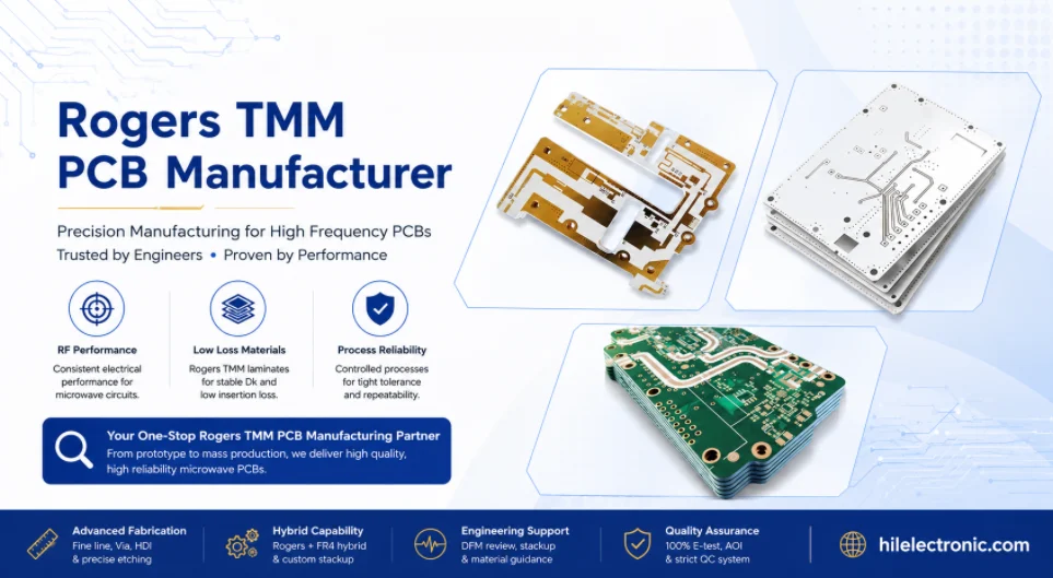
Highleap Electronics can support projects that require both PCB fabrication and PCB assembly. This helps align design intent, board construction and assembly method. For example, a connector launch can be reviewed for both RF geometry and soldering access. A power amplifier pad can be reviewed for thermal vias and solder void control. A shield frame can be checked against solder mask, copper clearance and board flatness.
RF connector and shield assembly
Many Rogers TMM boards use RF connectors or shield structures. Connector installation requires footprint accuracy, board edge quality, ground continuity, solder control and mechanical alignment. Shield assembly requires correct land pattern, flatness and thermal exposure planning. These features should not be treated as ordinary components when they are part of the RF performance path.
Highleap can review connector drawings, assembly notes and inspection requirements during PCBA preparation. For high-frequency assemblies, visual acceptance alone may not be enough. The project may require torque control, solder fillet inspection, X-ray inspection, continuity checks or customer-provided RF test procedure after assembly.
Thermal and grounding requirements in assembly
RF power boards, low-noise amplifier boards and microwave modules often require controlled grounding and heat flow. Thermal vias, copper pours, baseplate contact, heat spreaders and mounting holes should be reviewed with the assembly process. If a device has an exposed thermal pad, the solder paste design and via strategy should be compatible with both heat transfer and solder quality.
Grounding is also an assembly issue. Screws, shields, connectors, via fences and chassis contacts can create the final RF return path. The PCB fabrication drawing and assembly drawing should define plated mounting holes, surface finish, keepouts and mechanical contact areas. If the project requires conductive gaskets, thermal pads or metal housings, these interfaces should be reviewed before production release.
Cleaning, residues and handling control
Cleaning requirements should be defined for Rogers TMM assemblies. Flux residues near RF launches, filters, antennas or high-impedance nodes can affect reliability and measurement stability. Some finishes and assemblies require controlled handling to avoid tarnish, contamination or mechanical damage. The assembly process should match the material, finish and product environment.
Packaging after assembly is also part of quality control. RF boards may include exposed launch areas, precision connectors, delicate edges or tuned structures. Protective packaging should prevent scratches, contamination, bending and connector damage during shipping. For trial orders, packaging requirements can be simple; for production, they should be documented.
Component sourcing and consigned material coordination
Some customers provide RF connectors, active devices, shields or special components as consigned material. Others require component procurement support. Highleap can coordinate the assembly package based on BOM, approved manufacturer list, alternates and delivery schedule. For critical RF components, substitutes should not be purchased without approval.
Consigned material should be checked against quantity, packaging, moisture sensitivity, shelf life and assembly notes. A mismatch between component delivery and bare board delivery can delay PCBA. Coordinated planning between PCB fabrication and assembly reduces this risk.
Prototype, Trial Order and Production Transfer
Prototype build as engineering validation
A Rogers TMM prototype verifies more than board connectivity. It validates the real combination of laminate, copper, etch result, finish, via structure, connector launch and assembly method. Prototype results can include impedance measurement, insertion loss, return loss, antenna tuning, filter response, thermal behavior and assembly feedback. For details on early-stage builds, see the Rogers TMM PCB prototype page.
Prototype planning should identify the main risk being tested. If the risk is antenna tuning, patch dimensions and edge quality should be protected. If the risk is filter frequency, coupled gaps and resonator length should be inspected. If the risk is assembly, surface finish and connector soldering should be included. A prototype without a clear validation goal can produce boards but little useful production knowledge.
Trial order setup
A trial order can qualify the supplier before production release. It should use the real material grade, stackup, copper, finish, impedance requirement and assembly method whenever possible. If the trial order uses a simplified construction, that limitation should be recorded because the result may not fully represent production.
Trial order documentation should include the approved stackup, fabrication drawing, quote assumptions, DFM questions, measurement results, assembly feedback and any corrective actions. This documentation helps both sides decide whether the design is ready for pilot run or needs revision.
NPI review before first article
New product introduction connects engineering validation to repeatable manufacturing. Before first article production, Highleap can review open DFM issues, approved deviations, material availability, panelization, tooling, test requirements, assembly notes and packaging. The goal is to remove prototype uncertainty before the program becomes schedule-sensitive.
For Rogers TMM boards, NPI review should pay special attention to RF-critical features and process variables. The first article should not introduce a different finish, different copper profile, different mask opening or different coupon strategy unless the change is approved. A stable NPI package prevents prototype learning from being lost.
Production transfer control
Production transfer requires locked manufacturing data. The approved Gerbers, stackup, fabrication drawing, assembly drawing, BOM, finish, test requirements and packaging notes should all use the same revision. If a prototype measurement led to a line width adjustment, that adjustment should be incorporated into the released data rather than left as an informal note.
Repeatable Rogers TMM production depends on repeatable assumptions. Material grade, thickness, copper, finish, etch compensation, impedance coupon, routing method and inspection requirement should remain stable. Any change should be handled through documented engineering communication.
Scaling from small batch to volume
Small-batch and volume production change the cost structure and process planning. Material purchasing becomes more important. Panel utilization affects unit cost. Inspection sampling may be defined. Packaging and delivery schedule become more formal. Assembly line planning, component procurement and test capacity may also become important when PCBA is included.
Highleap can quote prototype, pilot and production quantities separately so the customer can see how cost and lead time change. A good production quote should state assumptions for material, finish, testing, documentation and delivery. Hidden exclusions create risk later.
Quality Control, Documentation and Change Management
Quality records for Rogers TMM PCBs
Quality documentation should match product risk. A simple development board may only need standard inspection and electrical test. A high-reliability RF product may require certificate of conformance, material traceability, impedance report, microsection report, plating thickness data, dimensional inspection and first article documentation. These requirements should be stated before quote approval.
Documentation helps connect the delivered board to the approved construction. If a board later fails RF measurement, the team can review material, stackup, copper, finish, etch result, hole quality and assembly notes. Without documentation, failure analysis becomes guesswork.
Inspection plan by project risk
Inspection should be chosen by function. Antenna boards may require dimensional inspection of patch length, feed gap and routed edge. Filter boards may require coupled gap and resonator length checks. Power RF boards may require plating quality, thermal via verification and flatness review. High-reliability boards may require microsection and thermal stress evidence.
Highleap can include inspection items in the production plan when they are specified. The customer should define acceptance criteria whenever possible. If only general workmanship is specified, the manufacturer can inspect for standard PCB quality, but not necessarily for RF-specific performance limits.
Change control after qualification
Qualified Rogers TMM PCB designs should be protected from uncontrolled changes. Material grade, dielectric thickness, copper foil, copper weight, surface finish, solder mask opening, etch compensation, via structure, board outline and assembly process can all affect RF performance. A change that looks minor commercially can be major electrically.
Highleap should communicate required changes through an engineering question or deviation request. The customer should approve or reject the change based on RF, quality and schedule impact. This process protects both sides from silent substitutions and inconsistent repeat lots.
Lot-to-lot repeatability
Repeatability requires the same approved manufacturing route. Lot-to-lot differences can come from material lot, copper surface, finish chemistry, etch result, drilling tool condition, plating thickness, assembly profile or component substitutions. Production records make these differences visible.
For long-term supply, retained build notes and controlled files are important. If a project has annual or multi-year demand, the customer should define which records must be stored and how repeat orders should be handled. Stable documentation reduces requalification effort.
Nonconformance and corrective action
When a Rogers TMM board has a quality issue, corrective action should identify the true failure mode. A detuned antenna, open via, cracked solder joint, excess insertion loss or connector mismatch can have different causes. The investigation may need material records, microsection, dimensional inspection, assembly profile and RF test data.
A useful corrective action does not only replace boards. It updates the process, drawing, inspection method or assembly notes to prevent recurrence. Highleap can support this process when the required records and acceptance criteria are defined.
Quote Package, Supplier Evaluation and FAQ
Complete Rogers TMM PCB RFQ package
A complete RFQ package helps Highleap quote Rogers TMM PCB manufacturing and assembly accurately. The package should include board data, material requirements, stackup, fabrication notes, assembly notes and quality requirements. Missing information does not only delay quotation; it can cause a quote based on assumptions that later need correction.
- Gerber, ODB++ or IPC-2581 manufacturing data.
- NC drill files and slot information.
- Fabrication drawing with board thickness, tolerance and acceptance class.
- Exact Rogers TMM grade and dielectric thickness.
- Copper weight, copper profile if required and surface finish.
- Layer stackup with reference planes and bond materials if hybrid.
- Controlled impedance table with line type, target and tolerance.
- Critical RF dimensions, antenna regions, launch details and mask keepouts.
- Coupon requirements for TDR, insertion loss, microsection or other tests.
- Quantity, lead time, prototype or production stage and delivery plan.
- BOM, pick-and-place file, assembly drawing and component notes for PCBA.
- Inspection records, CoC, traceability or first article requirements.
Quote comparison based on the same assumptions
Supplier quotes should be compared using the same construction and documentation requirements. One quotation may include impedance coupons, material traceability and microsection while another excludes them. One quotation may assume immersion silver while another assumes ENIG. One quotation may include PCBA connector installation while another is bare board only. These are different products, not just different prices.
Highleap can state quotation assumptions so the customer can compare scope clearly. A useful quote should identify material grade, thickness, finish, quantity, lead time, test items, assembly scope, documentation and exclusions. This reduces price revisions after order placement.
Supplier evaluation scorecard
A practical supplier scorecard can combine technical, quality, commercial and communication factors. The scorecard should not reward the lowest price alone. Rogers TMM boards often carry engineering risk, so the supplier that gives clearer assumptions and better production control may reduce total project cost even when the unit price is not the lowest.
| Evaluation area | Items to check | Why it matters |
|---|---|---|
| Material control | Exact TMM grade, thickness, source path and substitution approval. | Protects impedance, resonance, loss and qualified performance. |
| RF DFM | Stackup review, launch review, mask keepout and critical dimensions. | Prevents normal PCB edits from changing RF behavior. |
| Fabrication control | Etching, drilling, plating, routing and finish selection. | Protects yield, PTH reliability and measured RF performance. |
| Assembly support | BOM, connector soldering, shields, cleaning and packaging. | Connects bare board quality to usable electronic assemblies. |
| Quality documentation | CoC, impedance report, microsection, traceability and FAI. | Supports qualification, production transfer and failure analysis. |
| Commercial clarity | Scope, lead time, exclusions, packaging and re-order conditions. | Reduces hidden cost and schedule change after order release. |
Useful internal resources for project planning
Rogers TMM PCB projects often need several planning pages rather than one supplier page. For material performance and grade selection, see the Rogers TMM high-frequency PCB guide. For fabrication process details, see the Rogers TMM PCB fabrication guide. For prototype planning, see the Rogers TMM PCB prototype guide. For RF line and system-level use, see the Rogers TMM RF PCB page. For microwave circuits, see the Rogers TMM microwave PCB guide. For antenna projects, see the Rogers TMM antenna PCB page. For temperature reliability planning, see the Rogers TMM temperature stable PCB page.
RFQ release checklist
Before sending an order, confirm that the manufacturing package states the exact material, stackup, finish, impedance, test scope and assembly scope. This prevents a quote from being based on incomplete assumptions. For urgent projects, send prototype and production quantities together so Highleap can show cost and lead-time differences.
A complete RFQ allows faster engineering review and more accurate pricing. It also makes supplier comparison easier. To request a quotation, prepare the files and send them through the quick quote channel.
Rogers TMM PCB manufacturer FAQ
Does Highleap Electronics manufacture Rogers TMM raw laminate?
No. Highleap Electronics does not manufacture Rogers TMM raw laminate material. Rogers TMM is supplied by Rogers Corporation. Highleap manufactures and assembles PCBs using specified Rogers TMM laminates according to customer design and approved manufacturing files.
Can Highleap provide both Rogers TMM PCB fabrication and PCB assembly?
Yes. Highleap Electronics is a PCB manufacturing and PCB assembly electronic factory. Service can include bare Rogers TMM PCB fabrication, prototype boards, small-batch production, SMT assembly, through-hole assembly, connector installation and assembly coordination depending on the project files.
Which Rogers TMM grades can be used for PCB production?
Common Rogers TMM grades include TMM3, TMM4, TMM6, TMM10, TMM10i and TMM13i. The correct grade must be specified by the customer or approved during engineering review based on RF performance, size, stackup and manufacturing requirements.
What files are needed for a Rogers TMM PCB quote?
Send Gerber or ODB++/IPC-2581 data, drill files, fabrication drawing, stackup, material grade, copper weight, surface finish, impedance targets, quantity, lead time and test requirements. For assembly, also send BOM, pick-and-place data, assembly drawing and component notes.
Can Highleap also manufacture other PCB types?
Yes. Highleap Electronics manufactures and assembles many PCB types, including FR4 PCBs, high Tg PCBs, multilayer PCBs, HDI PCBs, impedance-controlled PCBs, flexible PCBs, rigid-flex PCBs, aluminum PCBs, copper substrate PCBs and other high-frequency PCB materials.

Recommended Posts

Taconic RF-35 PCB Manufacturing Service — Prototype Through Volume Production
Figure 1. Taconic RF-35 PCBTaconic RF-35 is the workhorse...

Isola Astra MT77 PCB Manufacturing
Figure 1. Isola Astra MT77 PCB ManufacturingIsola Astra...

Custom Rogers RO4835 PCB Fabrication & Assembly Services
Figure 1. Rogers RO4835 PCBRogers RO4835 PCB is a...

Nelco N4000-13 PCB Material and Manufacturing Guide | Highleap Electronics
Figure 1. Nelco N4000-13 PCBNelco N4000-13 PCB is a...
How to get a quote for PCBs
Let’s run DFM/DFA analysis for you and get back to you with a report. You can upload your files securely through our website. We require the following information in order to give you a quote:
-
- Gerber, ODB++, or .pcb, spec.
- BOM list if you require assembly
- Quantity
- Turn time
For PCBA services, please provide your BOM (Bill of Materials) and any specific assembly instructions. We also offer DFM/DFA analysis to optimize your designs for manufacturability and assembly, ensuring a smooth production process.