
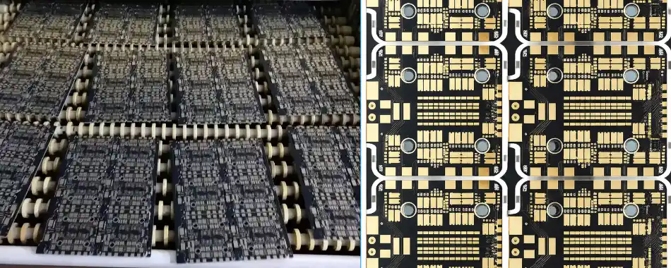
Fiber Optic Drone Circuit Board for Fiber-Guided UAV Systems

Fiber Optic Drone Circuit Board is commonly used in UAV systems built around a fiber optic spool or fiber canister. In these architectures, the board does more than carry optical data. It must also work reliably with the fiber deployment path, onboard processing electronics, connector structure, and the mechanical constraints of spool-based flight systems. This is why such boards differ fundamentally from standard RF drone communication hardware.
In practical applications, the board may support airborne optical data transmission, spool-side interface control, guidance signal handling, tether communication, or mixed video-and-telemetry links. The engineering challenge is not simply adding an optical transceiver to a UAV PCB. The board has to maintain signal integrity, connector stability, structural reliability, and assembly consistency inside a real fiber spool drone platform.
Get a Fiber Optic Drone Circuit Board Quote
Table of Contents
- Fiber Optic Drone Circuit Board in Fiber Spool UAV Systems
- What Makes It Different from a Standard Drone Communication Board
- Typical Board Types in Fiber Spool and Canister Architectures
- Design and Manufacturing Requirements
- Lead Time, Payment, and Delivery
- Related Fiber Drone PCB Categories
- Project Start Information
Fiber Optic Drone Circuit Board in Fiber Spool UAV Systems
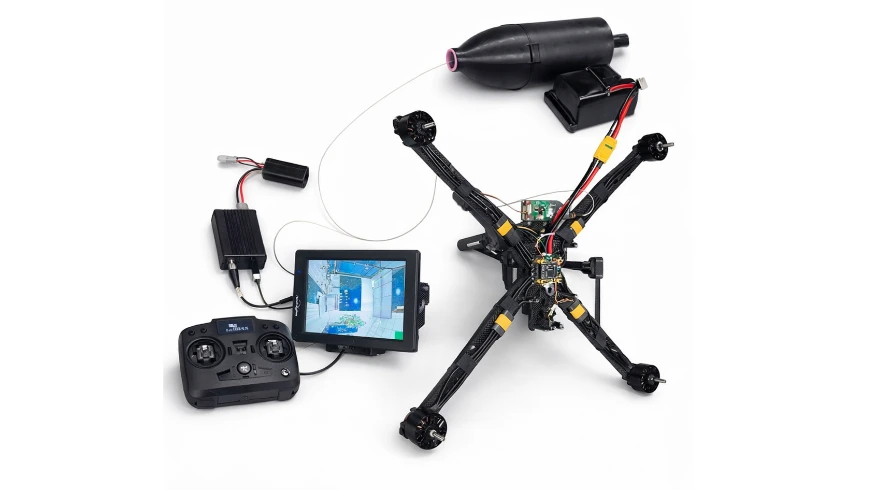
In many current applications, a Fiber Optic Drone Circuit Board is designed as part of a fiber optic spool-based or fiber canister-based UAV system. Instead of depending only on conventional radio communication, these platforms use a managed optical path for control, video, telemetry, or guidance-related data. That makes the board part of a larger deployment architecture rather than a standalone communication module.
Depending on the platform, the board may support:
- Electro-optical conversion between onboard electronics and the fiber path
- High-speed transmission of video, telemetry, and control data
- Interface coordination with a fiber optic spool, tether assembly, or canister
- Guidance or command-path processing in fiber-guided systems
- Power filtering and mixed-signal management inside electrically noisy UAV environments
The board often sits at the center of signal integrity, optical connectivity, and mechanical reliability. This is especially important when the fiber is actively deployed from a spool or controlled through a canister-type structure during operation. In such systems, board performance depends not only on the optical channel itself but also on how well the PCB integrates with the physical fiber-management architecture.
What Makes It Different from a Standard Drone Communication Board
A standard drone communication board is usually built around RF transmission. A Fiber Optic Drone Circuit Board in a spool-based system is built around a guided optical path instead. That changes the board-level priorities in several important ways.
First, the board requires an electro-optical transmit and receive path rather than a conventional antenna and RF front end. Second, it must maintain a mechanically stable interface to the fiber connection under vibration, motion, and structural stress near the spool or canister interface. Third, it often operates alongside spool-side control electronics, tether-related hardware, or fiber deployment constraints that are not present in ordinary wireless UAV systems.
These differences are why fiber spool UAV electronics cannot be treated as standard drone PCBs with an added optical module. The board has to be developed as part of a real optical-link system, with controlled routing, connector retention, structural alignment, and deployment-related reliability designed into the PCB from the beginning.
Why spool-based optical boards are more demanding
In a fiber spool UAV platform, the PCB is shaped not only by high-speed electrical requirements but also by the physical behavior of the deployed fiber path. Signal integrity, connector stability, vibration resistance, and board-to-spool interface reliability all have to be solved together.
Typical Board Types in Fiber Spool and Canister Architectures
Although many projects begin under the general label of Fiber Optic Drone Circuit Board, actual systems are usually divided into several board categories depending on where the electronics sit in the architecture.
| Board type | Main role | Typical system context |
|---|---|---|
| Airborne optical communication board | E/O conversion, video, telemetry, and control transmission | Tethered drone, fiber-linked UAV, optical payload platform |
| Fiber spool control board | Spool interface support, deployment control, auxiliary sensing | Fiber optic spool drone system or tether spool subsystem |
| Canister or ground-side support board | Dispensing support, operator-side interface, power coordination | Fiber canister platform or guided optical UAV system |
| Guidance and control board | Processes control or guidance signals over the fiber path | Fiber-guided UAV and related optical control architectures |
This is why one optical UAV program may extend into several specialized PCB categories. In many cases, the required board is more accurately aligned with a fiber optic tether spool PCB, a fiber-guided UAV control PCB, or a fiber optic canister PCB.
Design and Manufacturing Requirements
Designing and building a Fiber Optic Drone Circuit Board for a spool-based UAV system requires more than standard drone PCB capability. The board must combine high-speed electrical performance, optical interface stability, and mechanical compatibility with the deployment hardware around it.
Typical technical requirements include:
- Controlled-impedance differential routing for high-speed optical data channels
- Stable reference planes and clean power delivery for optical transmit and receive sections
- Fine-pitch support for FPGA, SoC, serializer/deserializer, processor, or imaging devices
- Mechanical retention and alignment stability at the fiber connector interface
- Board-level compatibility with fiber optic spool, tether, or canister-side structures
- Environmental protection processes that preserve optical connector cleanliness and mating performance
In systems that require stronger survivability in noisy or contested environments, the design may overlap with anti-jamming drone PCB considerations. Where the application is defense-oriented or hardened, it may also align more closely with military fiber drone PCB requirements.
The manufacturing side is equally important. A qualified supplier needs controlled stack-up fabrication, impedance verification, fine-pitch assembly capability, accurate optical connector-related mounting, and coating or protection workflows that do not compromise optical functionality. For these reasons, fiber spool drone boards fit naturally into advanced PCB fabrication and PCB assembly workflows rather than ordinary low-complexity UAV board production.
Why full application review matters
For spool-based optical drone boards, manufacturability depends not only on Gerber files and BOM data but also on how the board connects to the spool, tether, or canister hardware. Reviewing the complete application early helps prevent problems in connector choice, board layout, stack-up, and assembly planning.
Lead Time, Payment, and Delivery
Fiber Optic Drone Circuit Board projects often involve custom stack-ups, controlled impedance, specialized connectors, and mechanically sensitive optical interfaces. As a result, project execution is closely tied to lead time planning, payment arrangement, and delivery method, especially when the board is part of a spool-based UAV platform.
Lead time
Lead time depends on layer count, materials, impedance requirements, optical interface structure, component availability, assembly complexity, and the maturity of the design package. Prototype builds are generally shorter than production runs, but both are more accurate after reviewing PCB data, BOM files, assembly drawings, and spool or canister-related interface details.
Payment
Payment arrangement depends on project stage, order type, and commercial structure. Prototype runs, initial builds, and repeat production may follow different transaction processes depending on the program requirements and delivery region.
Delivery
Delivery planning should match the project stage and the physical sensitivity of the assembly. Prototype boards may require fast express shipment, while larger-volume orders may move through standard international freight channels. For optical assemblies with connector-critical regions or mixed mechanical parts, packaging method is also important to maintain surface condition, alignment stability, and structural protection during transport.
Related Fiber Drone PCB Categories
A general inquiry for Fiber Optic Drone Circuit Board may connect to several more specific board categories depending on the overall system structure. Related internal pages include:
- Drone optical data link PCB for transceiver-side optical data transmission
- Fiber optic tether spool PCB for spool-side or tether-related control electronics
- Fiber optic canister PCB for canister and dispensing-side hardware
- Fiber-guided UAV control PCB for control and guidance functions over the optical path
- Military fiber drone PCB for hardened defense-oriented optical UAV systems
In advanced compact platforms, the electrical design may also connect to specialized interconnect approaches such as glass interposer technologies, depending on routing density and package architecture.
Project Start Information
Project review for a spool-based optical UAV board is most effective when the board data is submitted together with the actual application context. Useful technical information usually includes:
- Gerber files, BOM, and assembly drawings
- Target data rate and optical interface details
- Layer count, impedance targets, and special material requirements if already defined
- Whether the board connects to a fiber optic spool, tether assembly, or canister structure
- Prototype quantity, production quantity, and target schedule
- Destination region and preferred delivery method
Providing these details early makes it easier to review PCB manufacturability, assembly feasibility, and the practical interface between the board and the spool or canister structure.
Submit your files through the Highleap quote form for design review, manufacturing assessment, and quotation.

Recommended Posts

Per-Key RGB Keyboard PCB Manufacturer & LED Assembly
A per-key RGB keyboard PCB manufacturer must control far...

Ortholinear Keyboard PCB Manufacturer | Custom Grid Layout
An ortholinear keyboard PCB manufacturer must preserve a...
Keypad PCB Assembly Manufacturer | Custom Control Keypads
A keypad PCB assembly manufacturer may be building a...
Keyboard Matrix PCB Design & Manufacturing | Anti-Ghosting
Keyboard matrix PCB design converts a large number of...
How to get a quote for PCBs
Let us run DFM/DFA analysis for you and get back to you with a report.
You can upload your files securely through our website.
We require the following information in order to give you a quote:
-
- Gerber, ODB++, or .pcb, spec.
- BOM list if you require assembly
- Quantity
- Turn time
In addition to PCB manufacturing, we offer a comprehensive range of electronic services, including PCB design, PCBA (Printed Circuit Board Assembly), and turnkey solutions. Whether you need help with prototyping, design verification, component sourcing, or mass production, we provide end-to-end support to ensure your project’s success. For PCBA services, please provide your BOM (Bill of Materials) and any specific assembly instructions. We also offer DFM/DFA analysis to optimize your designs for manufacturability and assembly, ensuring a smooth production process.